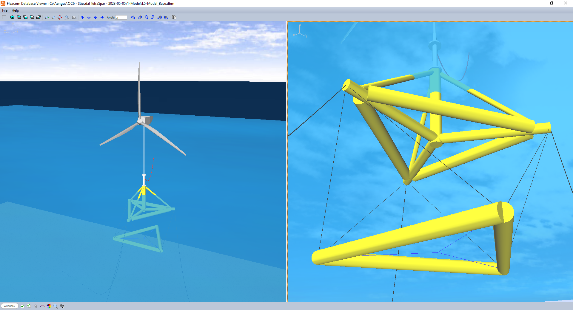
The Flexcom model of the model-scale Stiesdal Tetraspar examined at the University of Maine’s test environment is shown below.

Flexcom Model
The hull is modelled using a series of discrete Lines to represent the central column (CC), radial braces (RB), tri braces (HT) and diagonal braces (DB). These lines are connected up at appropriate points using a range of Equivalent Nodes to form a single coherent structure. Similarly the keel is built using Lines to model the tri braces (KT). The hull and keel and then linked together using 6 keel lines (KL), and further equivalent nodes.
Each line is assigned rigid Stiffness terms as the hull and keel are assumed to act as rigid bodies, apart from the keel lines which are highly flexible. The hull and keel components are assigned a Mass per Unit Length of zero (as the hull and keel masses are concentrated at their respective centres of mass). Each line is assigned a representative Buoyancy Diameter and Drag Diameter consistent with their physical sizes.
Suitable Point Mass and Rotational Inertia terms are specified at the hull and keel centres of gravity. Morison drag loads are primarily derived from the component drag diameters, but some additional viscous drag is modelled using Point Buoys located at the hull and keel centres of mass.
The mooring lines are created using 3 separate Lines. The upper end of each mooring line is attached to the relevant fairlead node on the hull using Equivalent Nodes, while the lower ends are constrained using Fixed Boundary Conditions. The mooring lines (and keel lines) are modelled using the Truss Element feature, which is ideally suited to modelling chains and wires. Realistic Stiffness, Mass per Unit Length, Buoyancy Diameter and Drag Diameter terms are assigned to the lines. Point Masses are included at the mooring fairleads to account for the presence of data sensors.
Similarly, the sensory umbilical is modelled using a catenary line. Some of its mass is assigned to the hull and tower, while the majority is distributed evenly along the umbilical line as a Mass per Unit Length.
Further lines are included to model the effects of the yaw bridles.
Tower & Rotor
The tower is constructed using a single Line, with its lower end attached to the hull using an Equivalent Node. The tower properties (e.g. diameter) vary as a function of height so it is modelled using several Line Sections, but the tower mass is concentrated at its centre of mass (via Point Mass and Rotational Inertia terms) so the Mass per Unit Length of each tower section is set to zero. Realistic Stiffness terms are individually assigned to each tower section based on the definition document.
The blades are kept at a fixed angle in all load cases, so there is no active control system in place and hence the *SERVODYN keyword is not present.