Rotor Blade Model |
 
|
Rotor Blade Model |
|
There are three options for modelling the rotor blades in Flexcom. You make your selection via *TURBINE ROTOR->BLADE MODEL.
This is a simplified RNA model in which the blade geometries are approximated as rigid profiles, so any variations in aerodynamic loading due to dynamic blade deformations are not captured. Blade rotational inertia is neglected as the blades are massless. If you are primarily interested in the global system response (e.g. platform motions, mooring line tensions etc.), and not necessarily concerned about the blade structural responses, the rigid blade model offers a very computationally efficient solution method as no finite elements are required for the blades. Refer to Example L04 - IEA 15MW RWT for an illustration of the rigid and flexible blade models.
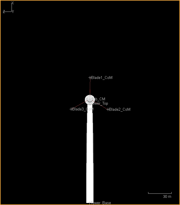
When you select BLADE MODEL=RIGID, the Flexcom GUI automatically creates:
•Three elements linking the hub to the (initial) centre of mass location of each blade
•Several elements to model the shaft and the shaft housing. As no blade rotation is being modelled, the shaft and its housing are fused together at each end via nodal equivalences
•One element connecting the shaft housing to the tower top (this is known as the yaw bearing element and allows the turbine to rotate)
•One element connecting the shaft housing to the centre of mass location of the nacelle
This is a more detailed RNA model in which the rotating blades are modelled explicitly using finite elements, capturing local blade deformations and their effects on aerodynamic loads. The (low speed) shaft is also modelled using beam elements. The shaft rotates within a rigid housing concentric with it, with the rotor bearings simulated using freely rotating hinge elements. Generator torque on the shaft is simulated using rotational damper elements. Blade pitch control is simulated using a torsional actuator feature which allows a twist to be applied to the blade root element without imparting any torsional strain to the blade structure. Yaw control is handled in a similar manner via the yaw bearing element. A related benefit of the flexible rotor model is that the rotational inertia of the blades is also captured. Additionally, in the case of a floating platform, the gyroscopic moment induced by the continually changing orientation of the rotor axis, caused by platform pitch and/or yaw in the ocean environment, is automatically included in the solution. Refer to Example L04 - IEA 15MW RWT for an illustration of the rigid and flexible blade models.
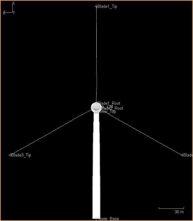
When you select BLADE MODEL=FLEXIBLE, the Flexcom GUI automatically creates:
•Numerous elements to model the blades, the total number for each blade is equal to the number of blade stations minus one. The blade root elements meet at the hub and are used to simulate pitch control.
•Several elements to model the shaft and the shaft housing. Hinge elements connect the shaft to its housing at each end, allowing free rotation of the shaft. Rotational dampers exist alongside the hinges and are used to simulate torque control and power extraction.
•One element connecting the shaft housing to the tower top (this is known as the yaw bearing element and allows the turbine to rotate)
•One element connecting the shaft housing to the centre of mass location of the nacelle
This was the only modelling option in software versions up to and including Flexcom 2022.1, and is retained for backward compatibility. If you choose this modelling option, it is your responsibility to create nodes (i) at the front end of the shaft (i.e. the hub), (ii) at the rear end of the shaft, (iii) at the nacelle centre of mass, and (iv) at the (initial) blade centre or centres of mass. You must also create elements to link each of these together in a coherent fashion. Refer to Example L01 - OC4 Semi-sub for an illustration of the manual blade model. We recommend that users migrate all turbine models to the rigid or flexible versions where possible.
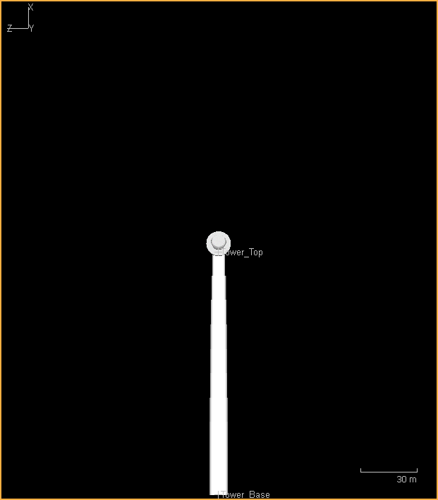
When you select BLADE MODEL=MANUAL, the Flexcom GUI will not automatically create any nodes or elements. All turbine components must be created manually.
The following images show what components you may expect to see automatically generated, as you alternate between the various options under *TURBINE ROTOR->BLADE MODEL.
Rigid Blade Model |
Flexible Blade Model |
Manual Blade Model |
|---|---|---|
|
|
|
If you are using the rigid or flexible blade models, high quality blade profiles are generated automatically using the information you’ve provided, including the aerofoil profile files, the positioning of the blade stations, the blade curvature angles, the aerodynamic twist angles, the structural twist angles, the chord lengths etc. If you wish to persist with the manual blade model, blade profiles will still need to be created manually using Customised Object Profiles built using XML (a tedious process) and linked to the Flexcom model using the *BODY,INTEGRATED keyword.
Keyword INPUTS
The following table summarises the keyword inputs required, depending on your selected blade modelling option.
Section |
Keywords |
Rigid Model |
Flexible Model |
Manual Model |
Purpose |
|---|---|---|---|---|---|
All |
ü |
ü |
ü |
A range of keywords relating to aerodynamic theory and modelling options. |
|
ü |
ü |
ü |
To construct the tower. |
||
ü |
ü |
ü |
To select blades profiles and specify related information, including the choice of blade model. |
||
ü |
ü |
û |
To specify information relating to hub, shaft, bearings and nacelle. |
||
û |
û |
ü |
For the manual blade model, you create elements to connect the tower to the shaft, to model the shaft (which connects the hub node), and to model the nacelle centre of mass. For the rigid and flexible models, all required nodes and elements are generated automatically. |
||
ü |
ü |
ü |
To specify the geometry of the turbine blades. |
||
ü |
ü |
û |
To specify the structural properties of the turbine blades. |
||
û |
û |
ü |
To specify an initial twist load of zero to the yaw bearing element (denoted Tower_To_Shaft) and the blade root elements (denoted Blade1_Root etc.). |
||
ü |
ü |
ü |
To provide a link between the Flexcom and AeroDyn. |
||
ü |
ü |
ü |
To provide a link between Flexcom and ServoDyn. |
||
ü |
ü |
ü |
To provide a link between Flexcom and InflowWind. |
Example L04 - Turbine Performance Test compares rigid and flexible blade models of the IEA 15MW turbine, supported by a tower only, without the floating platform and mooring system. It examines fundamental turbine performance characteristics as a function of wind speed, such as rotor thrust, rotor speed, generator torque, blade pitch and generator power. Generally speaking, close agreement is observed between the rigid and flexible blade models. Naturally only the flexible blade model is capable of presenting blade structural responses, such as tip deflections and root bending moments.
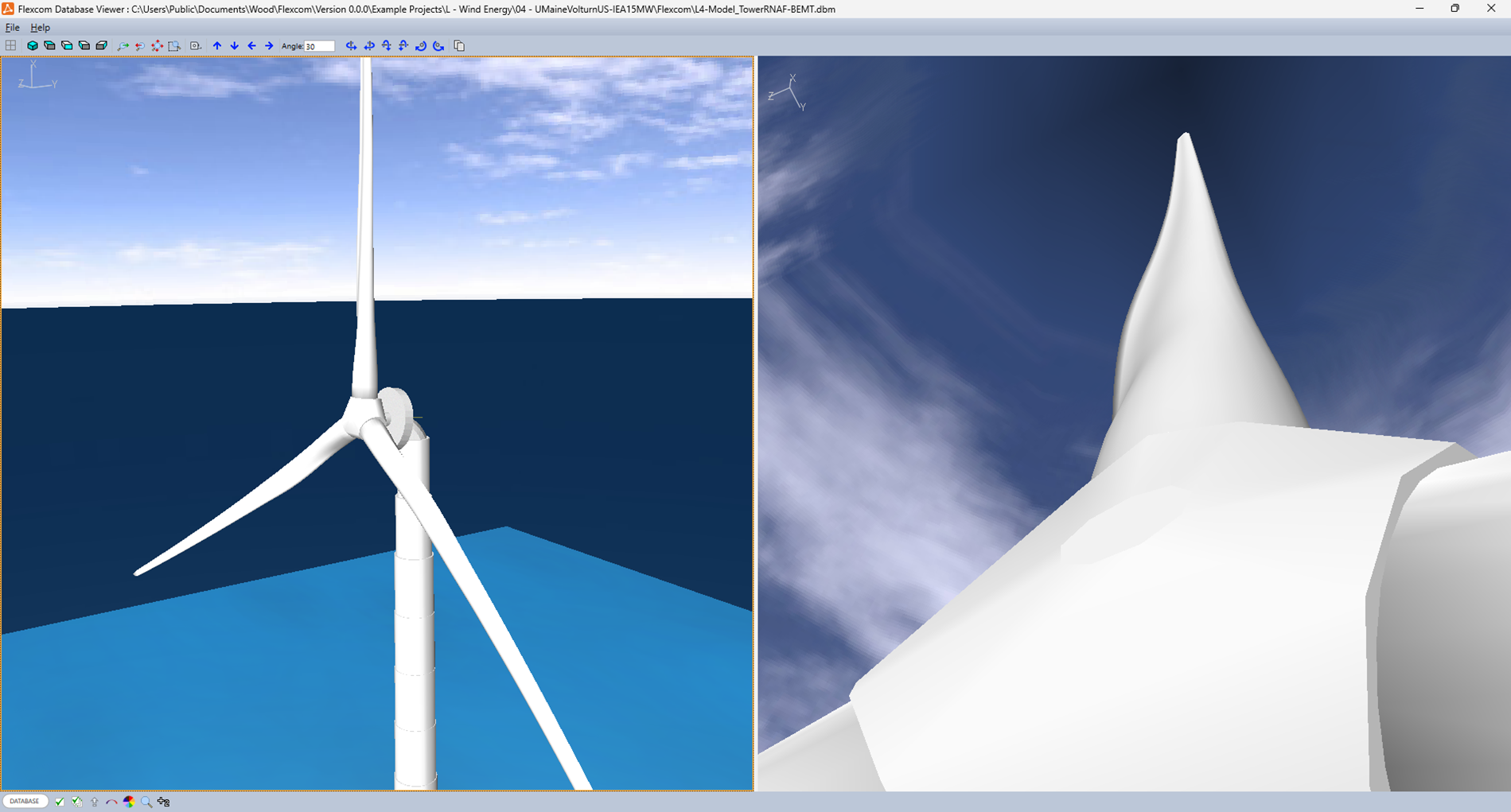
The following images show how the blades of the IEA 15MW RWT (117m in length) deform when the rotor is subjected to a wind speed of 10m/s (close to maximum thrust), and the rotor is spinning at about 5pm.

No Wind

10m/s Wind