|
*Node |
 
|
*Node
|
*Node |
|
To define nodal coordinates in the global Cartesian coordinate system.
Refer to Nodes for further information on this feature.
Note also that the old *NODE, *ELEMENT and *CABLE keywords have been largely superseded by the new *LINES keyword. Lines provide an automatic mesh creation facility to greatly expedite the model creation process. Using lines is a fundamentally different approach to working directly with nodes, elements and cables, although the information is ultimately handled in the same fashion internally. Since lines provide automatic mesh generation, you do not to concern yourself with explicit node and element numbering. Indeed the availability of lines makes nodes, elements and cables redundant to some degree, but they are retained for complete generality, and also to maintain downward compatibility with previous program versions. Refer to Lines for further information on this feature.
Two types of lines that may be mixed and/or repeated as often as necessary.
Line defining a single node:
Node, X Co-ordinate, Y Co-ordinate [, Z Co-ordinate]
Line generating a line of nodes between two existing nodes:
GEN=Start Node, End Node [, Node Increment]
Node Increment defaults to 1.
Input: |
Description |
Node: |
The node (number) being defined. |
X Coordinate: |
The nodal coordinate in the global X-direction. |
Y Coordinate: |
The nodal coordinate in the global Y-direction. |
Z Coordinate: |
The nodal coordinate in the global Z-direction. This defaults to a value of 0. |
Input: |
Description |
Start Node: |
The node (number) at the start of the straight-line segment. |
End Node: |
The node (number) at the end of the straight-line segment. |
Increment: |
The node number increment to be used in assigning numbers to the generated nodes. This input defaults to a value of 1, which will apply in the majority of cases. |
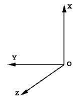
(a)The global Cartesian coordinate system is shown below and defines a right-handed system. Note that the global X axis is vertical in Flexcom.
(b)Node numbers do not need to be continuous in a Flexcom model - you can use any arbitrary scheme for assigning node numbers. This can be of considerable benefit when defining complex structures, such as for example multi-line riser systems, and can also greatly simplify the refining of a finite element mesh. Furthermore, as Flexcom incorporates automatic internal bandwidth optimisation, the node numbering scheme does not affect the analysis computation time.
(c)In certain circumstances, the coordinates specified here may represent only approximate nodal locations. This is the case when you use cables in defining the model geometry. For a more complete discussion, refer to Approximate Nodal Locations.
(d)The nodal coordinates specified here represent the initial position of the structure. This need not necessarily be an undeformed or stress-free configuration, although it will be in the majority of applications. For a more complete discussion, refer to Undeformed Versus Initial Positions.
(e)Node numbers are assigned to generated nodes by repeatedly adding the specified or default increment to the previous number (obviously starting at the start node), until the end node number is reached or exceeded. So for example, the specification Start node - 1, End Node - 11, Increment - 2 will result in 4 nodes, numbered 3, 5, 7 and 9, and dividing the straight line between nodes 1 and 11 into 5 equal segments.