Software Architecture |
 
|
Software Architecture |
|
The following schematic illustrates the software architecture, supported by the additional notes underneath.
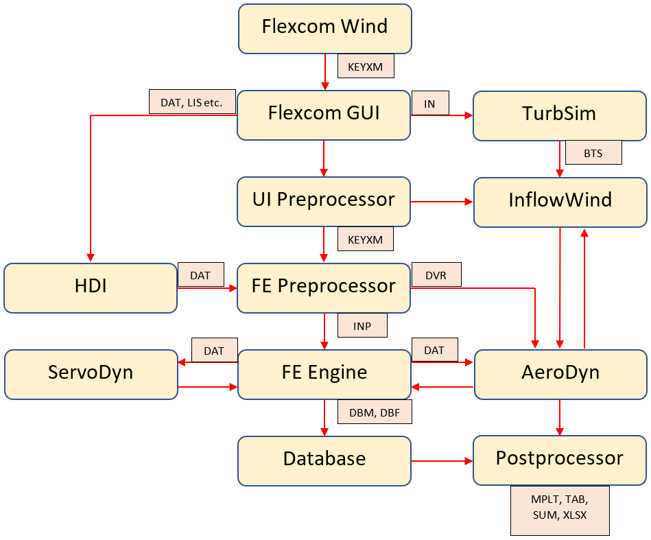
•Flexcom Wind is the dedicated user interface for model building of offshore wind turbines. It creates a well structured, heavily parameterised model in standard Keyword File format (KEYXM file) which can be subsequently edited within the main Flexcom GUI to meet individual requirements.
•Flexcom GUI is the main starting point for more experienced Flexcom users, who may already have template models built up from previous projects. It provides complete flexibility and control in terms of model building and running simulations.
•TurbSim, a full-field turbulent wind simulator, may be run from the Flexcom GUI. Flexcom creates input files (IN files) for TurbSim to model various wind conditions, and it creates a set of binary TurbSim files (BTS files) which contain wind field data as a function of space and time.
•UI Pre-processor, known as PreKey, is responsible for model generation within the Flexcom GUI. Its most important tasks are:
oFinite element mesh generation for lines
oPreliminary model solver based on a Runge-Kutta solution scheme
oPreparing a simplified keyword file (KEYXM file) to the FE Preprocessing module
oDisplaying the model preview in the Model View
•FE Pre-processor, known as ACM (analysis control module), is responsible for reading of keyword files (KEYXM) provided by the Flexcom GUI, processing and storing this data, and passing it on to the FE Engine (via the INP file, a file which the user is largely unaware of). It also creates the driver file (DVR file) which is used to initiate AeroDyn.
•FE Engine is the core computational module of Flexcom. It applies the finite element formulation to solve for the structural motions and forces. The FE engine interacts with AeroDyn (DVR file), InflowWind (DAT file) and ServoDyn (DAT file) at every solution time step, to ensure that the aerodynamic and structural models are fully coupled. Further details are provided in Software Couplings.
•Hydrodynamic Data Importer allows data to be imported from hydrodynamic simulation packages such as WAMIT and AQWA. It accepts input files such as OUT (WAMIT) and LIS (AQWA) etc. and creates a set of DAT files which are passed to the FE Preprocessor.
•Database Files are created by the FE Engine to store simulation results. DBM and DBF files are used to store motion and force data respectively.
•Postprocessor modules are used to extract information from the results database and display it to the user. The Database Postprocessor creates plot files (MPLT), tabular output files (TAB), and spreadsheets (XLSX). The Summary Postprocessor creates summary output files (SUM). Summary Collation creates summary collation spreadsheets (XLSX) and 3D plots (MPLT).
•Software Couplings provides more details regarding how Flexcom is coupled with the modules of OpenFAST.
•Rotor Blade Model outlines the differences between the simplistic rigid and advanced flexible rotor blade models.