*SERVODYN |
 
|
*SERVODYN |
|
To provide a link between Flexcom and FAST's wind turbine control module ServoDyn in a wind turbine simulation.
Refer to Coupling between Flexcom and ServoDyn for further information on this feature.
A block of lines which provides the key pieces of information to couple ServoDyn to Flexcom:
TURBINE SET=Turbine Element Set Name
ROTOR INERTIA=Rotor Inertia
GEARBOX RATIO=Gearbox Ratio
INPUT FILE=Path to ServoDyn input data file (.dat)
[FLEXCOM MANUAL OVERRIDE=Start Time, End Time, Min Blade Pitch, Max Blade Pitch, Min Generator Torque, Max Generator Torque, Blade Stiffness]
[Fl_Mode=Floating Feedback Axis System]
Floating Feedback Axis System can be TOWER-TOP or NACELLE (the default), corresponding to the Tower-Top/Base-Plate Coordinate System and the Nacelle/Yaw Coordinate System respectively in OpenFAST.
Input: |
Description |
Turbine Set: |
The portion (set of elements) of the finite element model which represents the turbine assembly which will be yawed by the yaw controller. See Note (a) |
Rotor Inertia: |
Rotational inertia of the rotors about the low-speed shaft which is |
Gearbox Ratio: |
The ratio of the high-speed to low-speed shaft speed. This value should be greater than zero and equal to unity for a direct-drive turbine. |
Input File: |
The path to the ServoDyn control data file. See the Turbine Component for additional details. |
Floating Feedback Axis System: |
The axis system in which the tower top acceleration terms are supplied by Flexcom to ServoDyn, be it the Tower-Top/Base-Plate Coordinate System (the default in OpenFAST) or the Nacelle/Yaw Coordinate System (the default in Flexcom). |
Input: |
Description |
Override Start Time: |
Time to start the manual override feature which gives you some further control over the model behaviour during the initial transient phase. By default, no overrides are modelled. |
Override End Time: |
Time to end the manual override feature. By default, no overrides are modelled. |
Override Min Blade Pitch Angle: |
The minimum blade pitch angle during the active time period. If a max angle is specified, min angle defaults to -90 degrees if not specified. |
Override Max Blade Pitch Angle: |
The maximum blade pitch angle during the active time period. If a min angle is specified, max angle defaults to 120 degrees if not specified. |
Override Min Generator Torque: |
The minimum generator torque during the active time period. If a max torque is specified, min torque defaults to 0 if not specified. |
Override Max Generator Torque: |
The maximum generator torque during the active time period. If a min torque is specified, max torque defaults to 1.0E+20 (i.e. infinite) if not specified. |
Override Blade Stiffness: |
The bending stiffness of the blade. |
(a)The turbine set should contain all elements contained in the nacelle assembly that are to be yawed about the tower vertical axis.
(b)All entries relating to Flexcom override feature are optional and by default no override is modelled. If either of the pitch entries are specified, then pitch control override is enabled, and each parameter is assigned a suitable default value if not explicitly specified (minimum = -90 degrees, maximum = +120 degrees). If either of the torque entries are specified, then torque control override is enabled, and each parameter is assigned a suitable default value if not explicitly specified (minimum zero, maximum infinite). If a blade stiffness value is specified, it applies to both the flapwise and edgewise directions.
(c)During the initial transient phase before the rotor has reached steady-state conditions, increasing the blade pitch angle or generator torque may be helpful in preventing rotor overspeed. Likewise, increasing the blade flexural stiffness may be helpful in preventing a tower strike. For a flexible blade model, the initial rotor speed is typically 0rpm as the rotor starts from a stationary position (unless you are using a restart). As the rotor accelerates, the blade pitch angle or generator torque provided by ServoDyn may not be sufficiently large to reduce the acceleration, resulting in significant rotor overspeed. Although temporary, the overspeed can result in wind forces and blade deflections which are unrealistically large, possibly leading to tower strike and simulation failure. Tower strike is not an issue for the rigid blade model, but large rotor speeds can trigger a critical Mach number error within the aerodynamic solver, again leading to premature simulation failure.
(d)Note also that ServoDyn includes a manual pitch override feature, which is fully integrated within the controller, but you would need to edit the ServoDyn input file to avail of this option. ServoDyn input files are text based and created manually outside of Flexcom. As you will typically consider a range of wind speeds, you could potentially require several ServoDyn input files, so you may find it easier to use the Flexcom override feature instead, which you can control from within the keyword file and parameterise with respect to wind speed if necessary.
(e)If you are using a generic controller like ROSCO, you are advised to use the latest available version, as newer versions tend to be more effective/responsive than older ones.
(f)OpenFAST supplies the tower top acceleration terms to the controller in the Tower-Top/Base-Plate Coordinate System, which translates and rotates as the platform moves and the tower bends, but does not yaw with the nacelle. Flexcom allows the user to choose between the tower system and the Nacelle/Yaw Coordinate System, which translates and rotates with the top of the tower, and also yaws with the nacelle. The rationale behind the Flexcom default is most readily explained via a simple example. Let's consider 3 separate models as follows:
1.Wind turbine model set up at 0 degrees. Steady wind applied at 0 degrees. The platform is forced to oscillate back and forth in the surge direction via a displacement-controlled sinusoidal boundary condition.
2.As per Model 1, but with the tower rotated by 90 degrees (e.g. simulation of a semi-sub yaw scenario). Note that the turbine also rotates with the tower. Steady wind applied at 90 degrees. The platform is forced to oscillate back and forth in the sway direction.
3.As per Model 1, but with turbine rotated by 90 degrees (e.g. simulation of a turbine yaw scenario). Note that the tower itself does not rotate. Steady wind applied at 90 degrees. The platform is forced to oscillate back and forth in the sway direction.
Hence in all 3 cases, the turbine is facing the incoming wind direction, and the platform is oscillating in the same direction. Floating feedback is enabled in the controller. One might intuitively expect all 3 models to have very similar behaviour if not identical.
▪If the tower top acceleration terms are supplied in the Tower-Top/Base-Plate Coordinate System, the blade pitch computed by ServoDyn is consistent between Models 1 and 2, but not consistent with Model 3 (in which floating feedback is effectively ignored).
▪If the tower top acceleration terms are supplied in the Nacelle/Yaw Coordinate System, the blade pitch computed by ServoDyn is consistent between Models 1, 2 and 3.
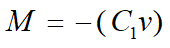 , the integral of the rotor (blades + hub + low-speed shaft) mass by the distance from the axis of rotation.