OC6 is an international research project sponsored by the International Energy Agency (IEA) and coordinated by the National Renewable Energy Laboratory (NREL). Its primary focus is verifying and validating numerical modelling tools employed in the analysis of floating offshore wind turbines. The key objectives (OC6, 2022) are:
1.Perform a three-way validation of both engineering-level and higher-fidelity offshore wind modelling tools through the comparison of simulation results to measured data from a series of experimental campaigns focused on specific physical phenomena.
2.Enhance the physics of the offshore wind modelling tools based on both the outcomes of validation campaigns, and the technology innovations which require the expansion of the tools' applicability and capabilities where limitations hinder technology advancement.
3.Determine longer-term research and development needs to comprehend the physics of offshore wind systems and how to integrate these attributes into the modelling tools.
The OC6 project consisted of four phases completed over four years from 2019-2023. Phase Ia was concerned with validating the nonlinear hydrodynamic loading on floating offshore wind support structures and Phase Ib dealt with additional data focused on Phase I from a component-level validation campaign geared toward computational fluid dynamic (CFD) simulation (Robertson et al., 2020). Phase II concentrated on developing and verifying an advanced soil-structure model for representing the pile-foundation interaction. Phase III was concerned with validation of the aerodynamic loading on a wind turbine rotor undergoing large motion caused by a floating support structure. Phase IV dealt with benchmarking and validating methods for combining potential flow and viscous hydrodynamic load models for novel floating offshore wind support structures (Bergua et al., 2023).
A range of simulation codes for offshore wind turbine modeling are represented in OC6 Phase IV, including: Opera, HAWC2, Bladed, OpenFAST, SIMA, DIEGO, OrcaFlex, 3dFloat, aNySIM-XMF, REFRESCO & ANYSIM-XMF, DARwind, Deeplines Wind, panMARE, FloawDyn and Flexcom.
A total of 17 academic and industrial partners from 10 different countries participated in OC6 Phase IV. Those actively involved were Bureau Veritas (BVMO, France), China State Shipbuilding Corporation (CSSC, China), Det Norsk Veritas (DNV, United Kingdom), Technical University of Denmark (DTU, Denmark), Dalian University of Technology (DUT, China), Électricité de France (EDF, France), Gavin & Doherty Geosolutions Ltd (GDG, Ireland), Institute for Energy Technology (IFE, Norway), Maritime Research Institute Netherlands (MAR, The Netherlands), National Renewable Energy Laboratory (NREL, United States of America), Newcastle University (NU, United Kingdom), PRINCIPIA (PRI, France), Shell (SHELL, United States of America), Hamburg University of Technology (TUHH, Germany), Universitat Politècnica de Catalunya (UPC, Spain), and Wood and University of Galway (W&UG, Ireland).
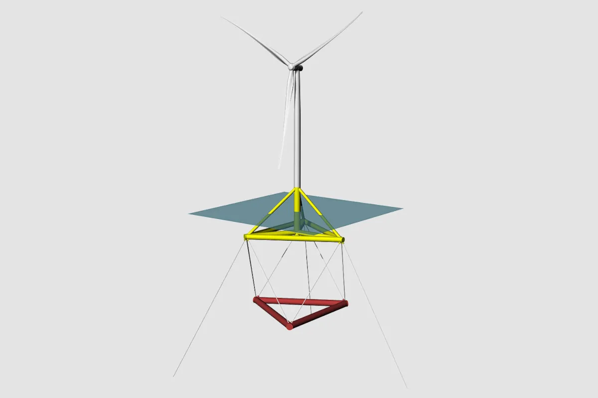
The ‘TetraSpar’, constructed by Stiesdal Offshore Technologies, was selected as the subject platform for OC6 Phase IV. A demonstrator version of the TetraSpar type structure was deployed off the coast of Norway in 200m deep water in 2021 (Stiesdal, 2021). The demonstrator platform supports a 3.6 MW Siemens Gamesa Renewable Energy wind turbine featuring a rotor diameter of 130m. The platform features a unique design with a low centre of gravity which gives the platform stability which is comparable to a spar, whilst retaining the construction and installation advantages of a semi-submersible. The platform is comprised of two separate steel sub-structures, a floating hull which supports the tower and wind turbine, and a keel which is suspended beneath the waterline. The lower keel structure has a high density and hence results in an overall low centre of gravity for the platform. The sub-structures (hull and keel) are connected via synthetic ropes which are referred to as keel lines. The structure is versatile and therefore, does not require deep-water ports. During assembly in port, employing the use of quayside cranes, the keel does not require to be deployed at full depth, thereby permitting the use of many more ports. Additionally, the tubular steel members are readily manufacturable and do not require welding during assembly.

Stiesdal Tetraspar (Stiesdal, 2021)
The following discussion is sourced directly from Bergua et al., 2023 with some minor adaptions.
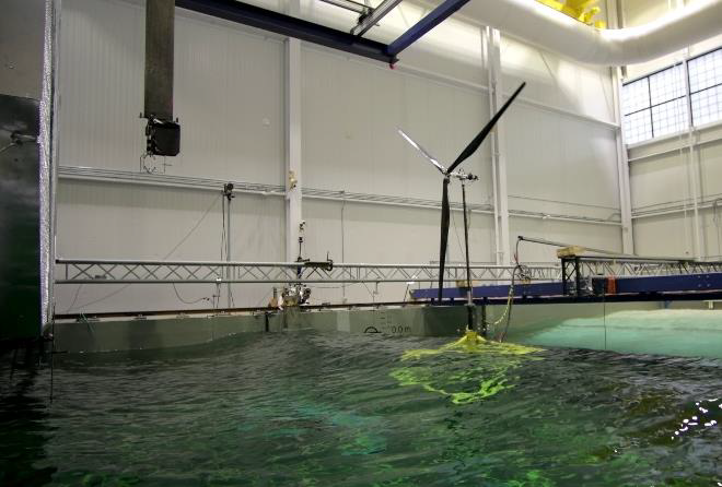
An experimental campaign was conducted at the Harold Alfond Wind-Wave (W2) Ocean Engineering Laboratory of the Advanced Structures and Composites Center at the University of Maine in December 2018 (Borg et. al, 2019). All the quantities in this section are given at full scale, except when specified otherwise. The basin is 30m long, 9m wide, and 5m deep (model scale), and is equipped with a 16-paddle wave maker opposite a beach and a bank of fans 7m wide and 3.5m tall (model scale). The testing used a 1:43 Froude-scale thrust-matched model of the 3.6-MW Siemens Gamesa wind turbine, with a rotor diameter of 129m, atop the TetraSpar floating support structure. This configuration is representative of the one used in the full-scale demonstration project by Stiesdal Offshore Technologies. The definition document of the OC6 Phase IV project (Wiley et al., 2023) provides information regarding the geometry and properties of the scale model.
The TetraSpar is made of two separate structures: hull and keel. The hull consists of a vertical central column (CC) directly beneath the wind turbine tower. At the base of the central column, there are three radial braces (RB) in the horizontal plane spaced 120° apart. Rigidity is given to this base with hull tri braces (HT) and diagonal braces (DB). The keel is made of three tri braces (KT) in the horizontal plane. The hull has a tetrahedral shape while the suspended keel has a triangular shape and acts as a system counterweight. Six taut cables, denoted as keel lines (KL), are used to link the hull and the keel. The system features a spar-like stability with the whole system center of mass located below the center of buoyancy. The lower the center of mass, the higher the gravitational restoring moments in roll and pitch degrees of freedom. This behavior is achieved thanks to the location of the keel (37.9 m below the hull) and its large mass (80% of the mass for the complete floating support structure).

TetraSpar 1:43 Scale Model (Bergua et al., 2023)
All members are cylindrical tubes and most of them are cone-shaped at one end (e.g., RB) or both ends (e.g., DB, HT, and KT). For reference, the HT, KT, and CC cylinders are 4.3 m in diameter. The CC is 32.15m long, the HT is 52.18m long, and the KT is 64.30m long. The hull center of mass is located 13.5m below the mean sea level while the keel center of mass is located 56.6m below the mean sea level. The center of buoyancy of the floating support structure is located around 33.8m below the mean sea level along the CC longitudinal axis. For this test campaign, the structural properties (e.g., members thickness distribution) were not known and therefore it was not possible to assess internal loading. Accordingly, participants considered the hull and keel as distinct rigid bodies and only included the flexibility of the keel lines within the floater.
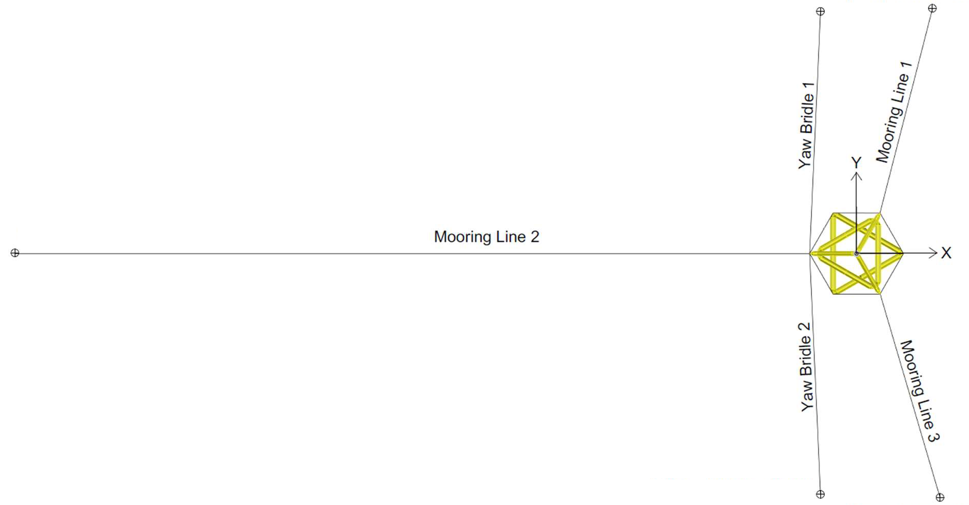
The mooring system consisted of three catenary lines. Each of the three lines was made of two different sections: a lower section made of heavier chain and an upper section of lighter chain. The two downwind lines (mooring lines 1 and 3) had to be truncated in the testing due to space limitations in the wave tank. The same configuration was replicated in the numerical models. The water depth considered is 193.5m. The upwind mooring line has a total length around 700m while the two downwind lines are each around 300m in length.

Mooring Arrangement in Tank (Wiley et al., 2023)
During the testing, one umbilical cable was used to transfer data and power between the system and the carriage in the wave basin. The presence of this umbilical had a large impact on the surge restoring force relative to that of the mooring system. This results in a significant shift of the surge eigenfrequency and change of the system dynamics. Therefore, one additional line was included in the numerical models to account for the umbilical.
The tower in the model test was made of aluminum and carbon fiber and was built to match a Froude-scaled first tower-bending eigenfrequency of the full-scale design. The tower length is around 76m, and its mass is 1.51×10⁵ kg.
The blades used in the testing were made of carbon fiber and were considered as rigid in the numerical models. The blades are 61.1m long and have a mass of 1.9×10⁴ kg. Information about the blade properties (e.g., twist, chord length, and airfoil thickness-to-chord ratio along the blade), airfoil polars (i.e., lift and drag coefficients for different angles of attack), blades mass, and blades center of gravity were provided in the definition document (Wiley et al., 2023). Properties of the nacelle as well as the complete RNA are also available in the definition document. The rotor shaft tilt angle is 0° and the RNA mass is 2.62×10⁵ kg. The total mass for the system (RNA, tower, and floating support structure including the fairlead tension sensors) is 6.08×10⁶ kg and the center of mass is located around 39.9m below the mean sea level.
The instrumentation during the testing campaign measured structural loads (e.g., tower base bending moments, keel line tensions, and fairlead tensions in the mooring lines), accelerations (e.g., tower top), tracking motion (e.g., keel and hull six degrees of freedom), and environmental conditions (e.g., wave elevation and wind speed). A complete list of the sensors used is also available in the definition document.
A stepwise validation procedure was performed in the OC6 Phase IV project taking advantage of the experimental campaign carried out by the University of Maine. The testing campaign used an open-loop control approach, where the rotor speed and the blade pitch angle were held constant. The scale model was subjected to a selected number of environmental load cases including, static equilibrium, free decay, wind only, wave only and combined wind and wave. The dynamic load cases were examined in three conditions, namely rated, post rated and storm conditions.
Section |
Load Case |
Description |
Wind Conditions |
Marine Conditions |
|---|---|---|---|---|
1.1 1.2 |
Equilibrium Surge Offset |
No wind No wind |
Still water Still water |
|
2.1 2.2 2.3 |
Surge Pitch Heave |
No wind No wind No wind |
Still water Still water Still water |
|
3.1 3.2 3.3 3.4 3.5 3.6 |
Rated (floating) Post-Rated (floating) Storm (floating) Rated (fixed) Post-Rated (fixed) Storm (fixed) |
Vx=9.89 m/s, Ω=12.2 rpm, β=−6.2° Vx=24.05 m/s, Ω=13.3 rpm, β=18.2° Vx=44.62 m/s, Ω=idling, β=89° Vx=9.89 m/s, Ω=12.2 rpm, β=−6.2° Vx=24.05 m/s, Ω=13.3 rpm, β=18.2° Vx=44.62 m/s, Ω=idling, β=89° |
Still water Still water Still water Still water Still water Still water |
|
4.1 4.2 4.3 4.4 |
Post-Rated Rated Post-Rated Storm |
Vx=0 m/s, Ω=0 rpm, β=0° Vx=0 m/s, Ω=0 rpm, β=0° Vx=0 m/s, Ω=0 rpm, β=0° Vx=0 m/s, Ω=0 rpm, β=0° |
Regular: H=8.31 m, T=12.41 s JONSWAP: Hs=1.46 m, Tp=6.73 s, γ=2.3 JONSWAP: Hs=8.00 m, Tp=12.20 s, γ=2.2 JONSWAP: Hs=12.81 m, Tp=15.79 s, γ=3.3 |
|
5.1 5.2 5.3 5.4 |
Post-Rated Rated Post-Rated Storm |
Vx=24.05 m/s, Ω=13.3 rpm, β=18.2° Vx=9.89 m/s, Ω=12.2 rpm, β=−6.2° Vx=24.05 m/s, Ω=13.3 rpm, β=18.2° Vx=44.62 m/s, Ω=idling, β=89° |
Regular: H=8.31 m, T=12.41 s JONSWAP: Hs=1.46 m, Tp=6.73 s, γ=2.3 JONSWAP: Hs=8.00 m, Tp=12.20 s, γ=2.2 JONSWAP: Hs=12.81 m, Tp=15.79 s, γ=3.3 |