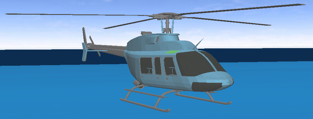
One additional feature relevant to setting up models in Flexcom is the use of so-called auxiliary bodies. Auxiliary bodies are not part of the finite element discretisation, but may be used to give a visual indication of the location of objects (such as floating vessels). So they are included for illustrative purposes only – they have no structural properties, you are not interested in determining forces or stresses within them, and they have no structural function whatsoever.
The coordinates of auxiliary nodes are defined in the global coordinate system in the normal fashion. Auxiliary nodes may be connected using auxiliary elements or auxiliary panels. Auxiliary elements are used for defining lines (each element connects two auxiliary nodes), while auxiliary panels are used for defining solid triangular surfaces (each panel connects three auxiliary nodes). It’s also possible to assign different colours (using standard RGB values) to different panels for enhanced visual displays. The coordinates of all auxiliary nodes and the connectivity of all auxiliary elements and panels must be defined directly – there are no associated generation facilities.
A group of auxiliary elements and/or panels can be grouped into an auxiliary body. Such bodies can then be associated with a vessel for which Response Amplitude Operators (RAOs) have been defined. The auxiliary elements and/or panels will translate and rotate with the vessel giving a clear representation of the motion of the vessel when viewed using the display facility.
Creation of individual auxiliary nodes, elements and panels can be quite tedious and time consuming. These concepts are somewhat outdated, and have effectively been superseded by the integrated vessel/body features which provide a range of standard vessel and subsea component profiles.
The profile is defined in XML format, and several sample profiles are available in your local Flexcom installation directory, under the sub-folder ‘StandardProfiles’. Each profile file contains a range of input data, capable of defining standard shapes such as boxes, cylinders etc., as well as arbitrary shapes defined by a series of points about which a mesh is constructed. All locations within the profile file are defined with respect to a local origin (0, 0, 0). The location of this origin in the global axis system is then defined by the X, Y, & Z coordinates of the body centre.
Refer to Creating Customised Object Profiles for further information on building your own models.

Post-processing
Auxiliary elements have existed since early versions of Flexcom. In terms of visualisation purposes, they have effectively been superseded by auxiliary panels and integrated vessel/component profiles. It should be noted however, that auxiliary elements do have one additional advantage – they may be referenced during postprocessing in the computation of element angles. For example, you may wish to monitor the angle between the riser at the vessel connection and some part of the vessel itself. Flexcom provides a range of outputs for this purpose under the general heading of Angles; a detailed discussion is provided in Angles Output.
Older keywords:
•*NODE,AUXILIARY is used to define auxiliary nodal coordinates in the global Cartesian coordinate system.
•*ELEMENT,AUXILIARY is used to specify the connectivity of auxiliary elements in the model.
•*AUXILIARY is used to specify the auxiliary elements which comprise an auxiliary body.
•*PANEL,AUXILIARY is used to specify nodes which are connected by an auxiliary panel.
•*PANEL SECTIONS,AUXILIARY is used to specify the auxiliary panels that make up an auxiliary body.
Newer keywords:
•*VESSEL,INTEGRATED is used to specify all information pertaining to a vessel. It offers a range of standard vessel profiles to provide enhanced visual appeal in the structural animation. You may choose to insert an FPSO, Semisub, Drill Ship, Spar, TLP, Installation Vessel etc. or opt to define your own customised vessel shape.
•*BODY,INTEGRATED is used to add subsea components to the structural animation for enhanced visual appeal.
If you would like to see an example of how these keywords are used in practice, refer to Example A01 - Deepwater Drilling Riser. Some samples images are shown for the Drill Ship and LMRP, BOP & Wellhead.