|
*Vessel,Integrated |
 
|
*Vessel,Integrated
|
*Vessel,Integrated |
|
To specify all information pertaining to a vessel or vessels.
Refer to Vessels and Vessel Motions for further information on this feature.
Note also that the old *VESSEL and *RAO keywords have effectively been superseded by the new *VESSEL,INTEGRATED keyword, which accepts RAO data also, thereby eliminating the need for a separate *RAO keyword – hence the ‘integrated’ nature of the new keyword.
A block of lines defining all information pertaining to a vessel.
The block begins with a mandatory line defining the vessel name. This is followed by an optional line specifying the theory used to combine vessel rotations. Next comes some optional lines associating RAO data with the vessel. This is then followed by further optional lines associating a predefined profile with the vessel. The entire block may then be repeated for subsequent vessels.
Mandatory line defining the vessel name and its physical location:
VESSEL=Vessel Name
Optional line specifying the theory used to combine vessel rotations:
Mandatory line defining the initial position of the vessel’s focal point, and the initial yaw orientation of the vessel:
INITIAL POSITION=X, Y, Z [, Initial Yaw]
Optional line associating RAO data with the vessel:
[RAO=RAO File Name][, FORMAT=Format Name][, UNITS=Unit Type]
Optional line defining separation between the focal point and the RAO reference point (the point on the vessel for which the RAOs are defined), specified in the local vessel heave, surge and sway directions:
[REF=REF X, REF Y, REF Z]
Optional line associating a predefined profile with the vessel:
[PROFILE=Profile Type]
If the profile type is user-defined, then another mandatory line immediately follows:
FILE=Profile File Name
Optional line defining overall dimensions for the vessel profile:
[DIMENSIONS=Height, Length, Width]
Optional line defining separation between the focal point and the centre of the vessel profile, specified in the local vessel heave, surge and sway directions:
[COP=COP X, COP Y, COP Z]
Angles Theory may be LARGE (the default) or SMALL. Initial Yaw defaults to zero. Angles Theory may be LARGE (the default) or SMALL. If a file name or any part of its path contains spaces then it should be enclosed in double quotation marks. Format Name may be one of the standard program formats (MCS, AQWA, WAMIT, MOSES or ORCAFLEX) or the name of a customised format defined under *RAO FORMAT. Unit Type is only relevant to the standard program formats (apart the standard MCS format). REF X, REF Y, REF Z, COP X, COP Y and COP Z all default to zero. If dimensions are not explicitly defined, some generic dimensions are applied automatically to the body.
Input: |
Description |
Vessel Name: |
A descriptive name for the vessel. |
Focal Point X, Y, Z: |
The global X, Y, & Z coordinates of the vessel’s focal point at solution initiation. Strictly speaking, it defines the point about which the initial yaw orientation of the vessel is applied. In many cases, the focal point will be coincident with both the RAO reference point (the point on the vessel for which the RAOs are defined) and the centre of the vessel profile (which provides enhanced visual appeal in the structural animation). See Note (a). |
Yaw: |
The initial undisplaced orientation of the vessel, specified in degrees anticlockwise from the global Y-axis. This defaults to a value of 0°. |
RAO File: |
The name of the ASCII file containing the RAO data. |
Format: |
The format of the RAO data. You may select from a range of standard program formats, or alternatively reference a customised RAO format, in which case you specify the name of a predefined RAO Conversion. See Note (b). |
Units: |
If you are using one of the standard program formats (apart the standard MCS format), it is advisable to explicitly specify the unit system used in the external RAO file. Flexcom will attempt to ascertain the unit system from the external file, but as this is not always possible, you are advised to explicitly state the unit system in order to avoid any possible ambiguity. |
Reference Point Offset X, Y, Z: |
The physical separation between the focal point and the RAO reference point (the point on the vessel for which the RAOs are defined), specified in the local vessel heave, surge and sway directions. See Note (a). |
Profile: |
The profile type used to represent the vessel. You may choose from a range of standard profiles, or opt to use a customised profile. |
User Profile: |
If you are using a customised profile, this input defines the location of the profile file. See Note (d). |
Height, Length, Width: |
The overall dimensions of the profile in the local heave, surge and sway axes. If dimensions are not explicitly defined, some generic dimensions are applied automatically to the vessel. |
Centre of Profile Offset X, Y, Z: |
The physical separation between the focal point and the centre of the vessel profile (which provides enhanced visual appeal in the structural animation), specified in the local vessel heave, surge and sway directions. See Note (a). |
Angle Theory: |
The theory used to combine vessel rotations. The options are Large Angles (the default) and Small Angles. |
Notes
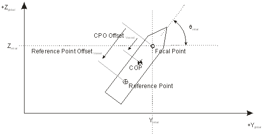
(a)The Focal Point defines the initial position of the vessel at solution initiation. Strictly speaking, it defines the point about which the initial yaw orientation of the vessel is applied. By default, the focal point is coincident with the RAO reference point (the point on the vessel for which the RAOs are defined), but you may also define Reference Point Offset terms if this is not the case. Likewise, the vessel profile is also centred about the focal point (i.e. the origin used in the definition of the profile is assumed to be coincident with the focal point), but again you may define Centre of Profile Offset terms if this is not the case.
Note that the Focal Point entries define a physical location in global X, Y, & Z coordinates. Both the Reference Point Offset and the Centre of Profile Offset define physical separations with respect to the focal point, specified in the local vessel heave, surge and sway directions, respectively.
The following figure illustrates the various inputs graphically. It shows a turret moored vessel in plan view. Note that the initial location of the RAO reference point, and the initial configuration of the vessel profile, are both governed by the initial location of the focal point, the applied initial yaw orientation. This facility allows you to adjust the initial orientation of the turret moored vessel without affecting any attached risers, jumpers or mooring lines.
(b)Supported programs include AQWA, WAMIT, MOSES and OrcaFlex. If you specify any of these program names as an RAO format, the program’s standard output file may be used directly as a source of RAO data. Flexcom understands the conventions used in these programs and automatically performs the relevant conversions for you. For further details regarding the conventions assumed for each of these programs, refer to RAO Conversions. MCS is also a pre-defined format, which represents the standard RAO conventions traditionally used by Flexcom.
If you RAO data does not correspond to any of these standard conventions, you may explicitly define some customised conventions via an RAO conversion (*RAO FORMAT keyword). In this case, you should define the RAO data in an ASCII file, in a layout similar to the standard MCS or Line layouts, and use the Format input above to reference the required RAO conversion. Refer to MCS Layout and Line Layout for further details.
(c)Flexcom uses linear interpolation to calculate RAOs and phase angles at wave headings and frequencies intermediate to those in the RAO file. Outside of the range of user-specified headings and frequencies, RAOs and phase angles are assumed to be zero, so it is important to ensure you cover the full range of conditions likely to be encountered in an analysis when inputting the RAO data.
In the standard MCS convention, wave heading is defined as the angle between the direction of approach of a wave harmonic incident on the vessel and the local surge axis. However, please note that in strict mathematical terms the incident wave heading is the angle between the wave direction drawn at the vessel reference point and the negative direction of the local surge axis. Phase angles are specified in degrees, and represent a phase lag or lead relative to the wave at the vessel reference point. A positive phase angle denotes a phase lag relative to the incident wave harmonic.
(d)The profile is defined in XML format, and several sample profiles are available in your local Flexcom installation directory, under the sub-folder ‘StandardProfiles’. Each profile file contains a range of input data, capable of defining standard shapes such as boxes, cylinders etc., as well as arbitrary shapes defined by a series of points about which a mesh is constructed. All locations within the profile file are defined with respect to a local origin (0, 0, 0). The location of this origin in the global axis system is then defined by the Focal Point and Centre of Profile Offset entries as discussed in Note (a). Should you require any assistance in creating your own customised profile, feel free to contact sw.support@woodgroup.com and our support team will discuss the format of the XML information in more detail.