*LINE PATHS is a modelling feature which makes it easy to model a line with an arbitrary geometrical configuration e.g. such as a rigid spool. Note that the Lines modelling feature is better suited to modelling straight lines or simple catenary sections.
The main aspects to defining a line path are...
•Line
▪Line name
▪Start point name and location (global XYZ coordinates)
▪End point name
▪General finite element mesh settings for the entire line
•Line segments
▪Corner locations (relative XYZ coordinates with respect to the previous corner or line start)
▪Corner radii
▪Tangent lengths (regions adjacent to each bend for which corner meshing settings also apply)
▪Finite element mesh settings for the corners and intermediate straight portions
•Line sections
▪Start and end locations (defined in terms of virtual distances from the line start or end)
Please note that line segments govern the physical geometry and finite element meshing of the line path. They also result in the automatic creation of element sets (and node/element labels), facilitating the subsequent assignment of geometric and hydrodynamic properties. Additional element sets may be created via *LINE PATH SECTIONS if required.
It is important to use meaningful entries for line names, start and end locations, segment names, section names etc., as these names will be used by the program to automatically create node/element labels and element sets. Node labels may be referenced subsequently when you are applying boundary conditions or point loads, while element labels may be referenced during postprocessing operations. Similarly, element sets may be referenced when you are assigning structural and hydrodynamic properties to your model.
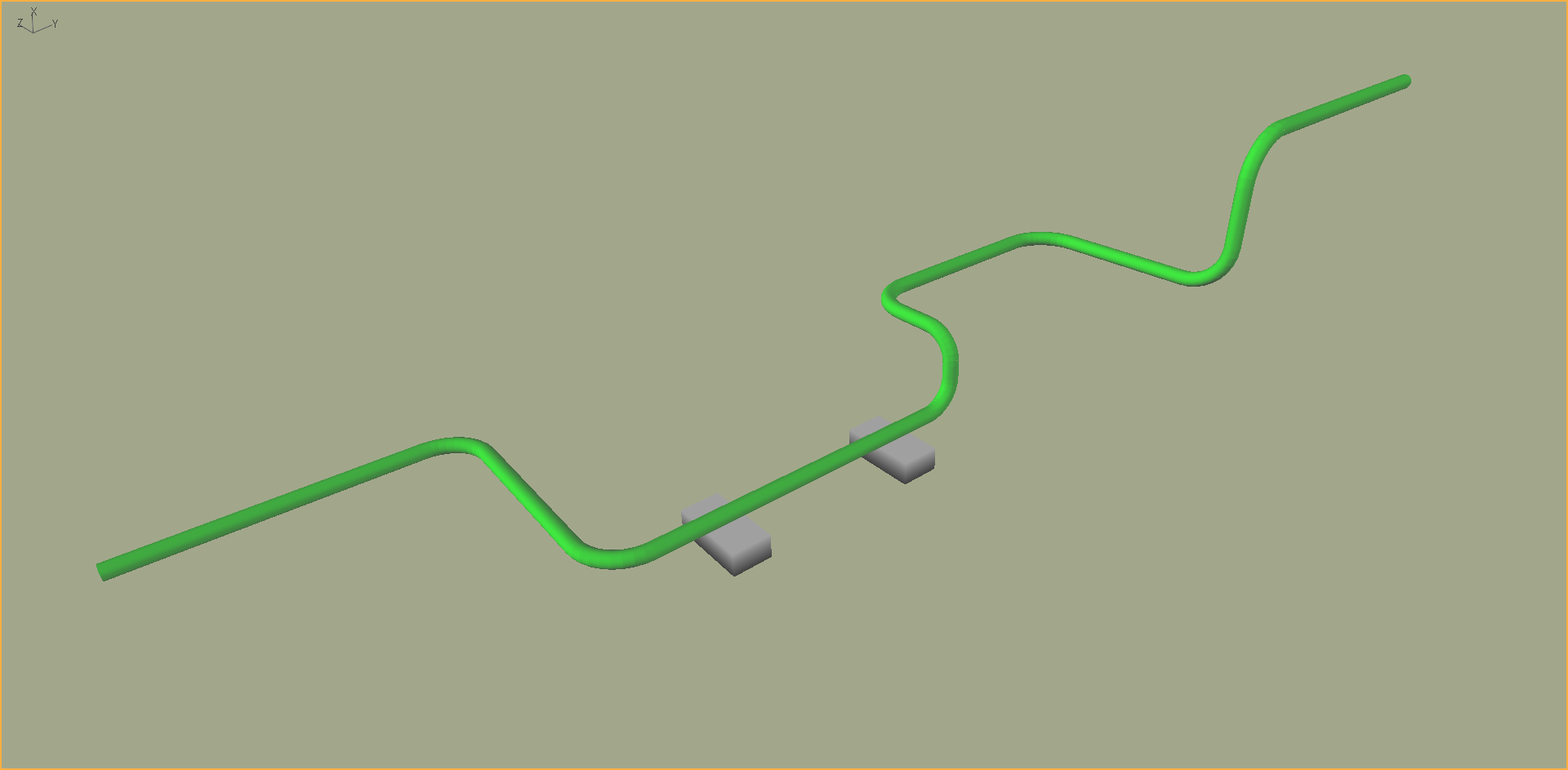
For illustrative purposes, let's consider the rigid spool model shown below, taken from Example G03 - Rigid Spool.

Fig.1: Rigid Spool
General information regarding the line path is specified in the opening block of *LINE PATHS, and/or the Line Paths table.
•Lines may be assigned generic names like “SpoolA”, “SpoolB” etc., or perhaps more specific names like “WestSpool1”, "SouthSpool1” etc. Flexcom creates an element set corresponding to each line name e.g. "SpoolA".
•The start and end points might be called something like "SpoolA_Start" and "SpoolA_End", or "SpoolA_Lower" and "SpoolA_Upper", respectively. These names will be used by the program to automatically create relevant node labels which you can reference when applying boundary conditions or point loads to your model. Element labels are also created automatically to identify the first and last elements of each line path e.g. "SpoolA_First" and "SpoolA_Last".
•Note that the start location is defined in terms of global XYZ coordinates. It is not necessary to define an end location, as this will be determined by the cumulative summation of the (relative) corner locations to be discussed presently.
•General mesh settings for the entire line are specified as part of the general line parameters. See Mesh Generation for an illustration.
•Local undeformed axes for the line may be explicitly assigned to the line via the V and W vector inputs. These entries are optional and should be left blank in the vast majority of cases. Refer to Lines & Local Undeformed Axes for further discussion on the significance of the V and W vectors, including the unusual situations where you may need to invoke them.
Information regarding segments of the line path are specified in the segment block of *LINE PATHS, and/or the Line Path Segments table. Line segments govern the physical geometry and finite element meshing of the line. They also result in the automatic creation of element sets (and node/element labels).
•Line segments may be assigned generic names like “Segment1”, “Segment2” etc., or perhaps more specific names like “Seabed1”, “Seabed2”, “Vertical1” etc.
•Corner locations define the location of each segment end. The coordinates are specified with respect to the end point of the previous segment, or the line start point in the case of the first segment. So these are relative XYZ positions rather than absolute.
•The corner radius governs the radius of curvature of the corner segment. Specification of the corner radius is optional and it defaults to 3 times the local element diameter if the entry is left blank. Should you wish to model a 90 degree bend, you should specify a very small value for corner radius (e.g. 0.0001) as any value below 0.001 is ignored by the mesh generator.
•The tangent length defines the length, before and after the bend, to which the corner meshing settings also apply. This allows you to use a refined mesh beyond the extents of the bend radius. Specification of the tangent length is optional and it defaults to 500mm or 20inch if the entry is left blank. Should you wish to treat the tangent segment like the straight section, you should specify a very small value for tangent length.
•Flexcom creates an element set corresponding to each segment straight and corner portions e.g. "Segment1_Straight" and "Segment1_Corner". It also creates element sets which contain all the elements in the straight (e.g. "SpoolA_Straight") and corner sections (e.g. "SpoolA_Corners") for a given spool. The corner sets include the tangent portion on either side of the corner. Flexcom also creates node labels at the start and end of every segment (e.g. "Segment1_Straight_Start", "Segment1_Straight_End"), and at the mid-point of each corner (e.g. "Segment1_Corner_Mid".
•Specification of the element lengths around the corner is optional and if the entry is left blank, the default element length is such that there is approximately 1 element for every 5 degrees of bend. Mesh settings for the straight line segments in between the corners are also specified as part of the line segment parameters. See Mesh Generation for an illustration.
•Local undeformed axes for the line segment may be explicitly assigned to the line via the V and W vector inputs. These entries are optional and should be left blank in the vast majority of cases. Refer to Lines & Local Undeformed Axes for further discussion on the significance of the V and W vectors, including the unusual situations where you may need to invoke them.
Information regarding sections of the line path are specified in *LINE PATH SECTIONS, and/or the Line Path Sections table. Line sections result in the automatic creation of additional element sets.
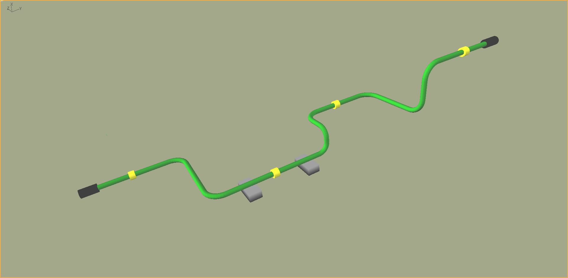
•If you model has uniform properties throughout, like the spool shown in Figure 1, you do not need to define any line sections. However, if you model has additional attachments, like the spool shown in Figure 2, then you may wish to define sections as demonstrated below. For this example, you may reference the set names "End Fittings" and "Clamps" when assigning geometric and hydrodynamic properties.
o*LINE PATH SECTIONS
o SECTION=Lower End Fitting, <0m>, <1.3m>
o ADDITIONAL=End Fittings
o SECTION=Clamp1, <3.7m>, <4.1m>
o ADDITIONAL=Clamps
o SECTION=Clamp2, <15.2m>, <15.7m>
o ADDITIONAL=Clamps
o SECTION=Clamp3, <22.6m>, <23.1m>
o ADDITIONAL=Clamps
o SECTION=Clamp4, <33.3m>, <33.8m>
o ADDITIONAL=Clamps
o SECTION=Upper End Fitting, <36.1m>, <37.5m>
o ADDITIONAL=End Fittings

Fig.1: Rigid Spool with End Fittings and Clamps
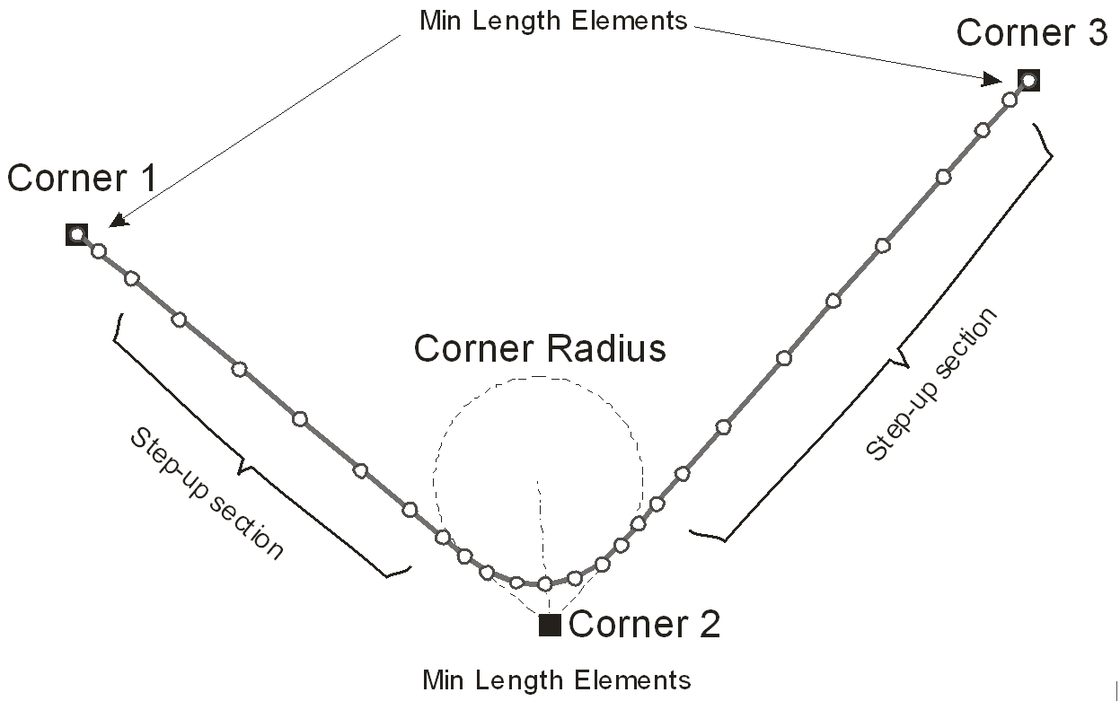
You have control over the distribution of the elements along the line, via the specification of corner element lengths, maximum and minimum element lengths for the entire line and for each of its individual segments. The meshing algorithm automatically generates a finite element discretisation based on the guidelines you provide. Ideally, the aim is to create a mesh which is sufficiently dense to accurately capture structural behaviour, while not being unduly complex. Figure 3 schematically illustrates the line path meshing.
The meshing algorithm also attempts to prevent large changes in relative element length across the finite element mesh by gradually stepping up and down element lengths along the structure, and to avoid over-meshing by using longer elements in the middle of long sections of continuous properties. Corner sections, and intersections between different line segments, are generally the points of most interest and therefore have a more refined mesh. It is desirable to step up the element lengths away from these regions and use larger elements towards the centre of homogenous sections. The meshing algorithm ensures that the ratio between the lengths of adjacent elements cannot exceed a certain value. The maximum ratio defaults to 1.5 (Standard option), but may be reduced to 1.25 (Fine option) or 1.1 (Super Fine option). The actual value of the ratio is automatically selected to correctly fill the meshed section with elements.

Fig.3: Line Path Meshing
Users who are interesting in gaining a fuller understanding of the meshing strategy are referred to Meshing Algorithm. Although this article is written in the context of Lines rather than Line Paths, the underlying meshing philosophy is consistent in both cases. Line paths introduce the additional complexity of corner sections, but otherwise the meshing algorithm operates in a similar manner to that of lines (both methods actually share a lot of common source code in the Flexcom GUI pre-processor).
One further point to note is that the automatic meshing algorithm allows you to request that nodes be positioned exactly at specific lengths along a line path. This is in addition to the guidelines you provide in relation to desired element lengths for the corners and straight sections. For example, if you wish to apply a point load at a certain distance along a line path, or to connect another component (e.g. another line) at a specific location, you would typically position a node on the line path at the required location. Meaningful names should be specified as these names will be used by the program to automatically create relevant node labels.
It is important to note that any distances associated with line paths (such as the start or end distance of a sub-section, or the distance of a line location point) are virtual rather than physical. This means that you should always specify distances on the assumption that all corners have zero bend radius. For example, the physical distance between Corner 1 and Corner 3 in Figure 3 is L1 + (0.5*π*R) + L2, where L1 and L2 are the lengths of the straight sections and R is the bend radius at the corner. But if you wished to define a sub-section which started at Corner 3, then the distance you would specify under *LINE PATH SECTIONS would be L1 + (2*R) + L2. While this modelling approach may seem unusual at first, it ensures that the definition of sub-sections is independent of bend radius, and allows you to examine bend radii of various sizes during the design process without having to redefine the overall model.
•*LINE PATHS is used to define a line with an arbitrary geometrical configuration (e.g. such as a rigid spool).
•*LINE PATH SECTIONS is used to define sections within a line path with a view to generating additional element sets. This keyword is closely linked to *LINE PATHS.
•*LINE LOCATIONS is used to define named locations along a line, allowing you to request that nodes be positioned exactly at specific lengths along a line.
If you would like to see an example of how these keywords are used in practice, refer to Example G03 - Rigid Spool.