The specification of the components of the vectors V and W is related to the Flexcom facility for analysing a structure which is initially deformed. Basically, you specify V and W explicitly when the configuration defined by the nodal coordinates you have input does not represent a stress-free structure orientation. However, in the majority of analyses, this is not the case, and the specified nodal coordinates do represent the undeformed as well as the initial position. In this situation, the specification of V and W is optional, and should in general be omitted. If you want to enter V and W values then all of the values V1, V2, V3, W1, W2, and W3 must be entered. When you do not define V and W explicitly, Flexcom calculates nominal values for these vectors using a default algorithm, based on the specified nodal coordinates. The significance of the V and W vectors, which define the undeformed element orientations, is the same regardless of whether you are using *ELEMENT, *LINES or *LINE PATHS.
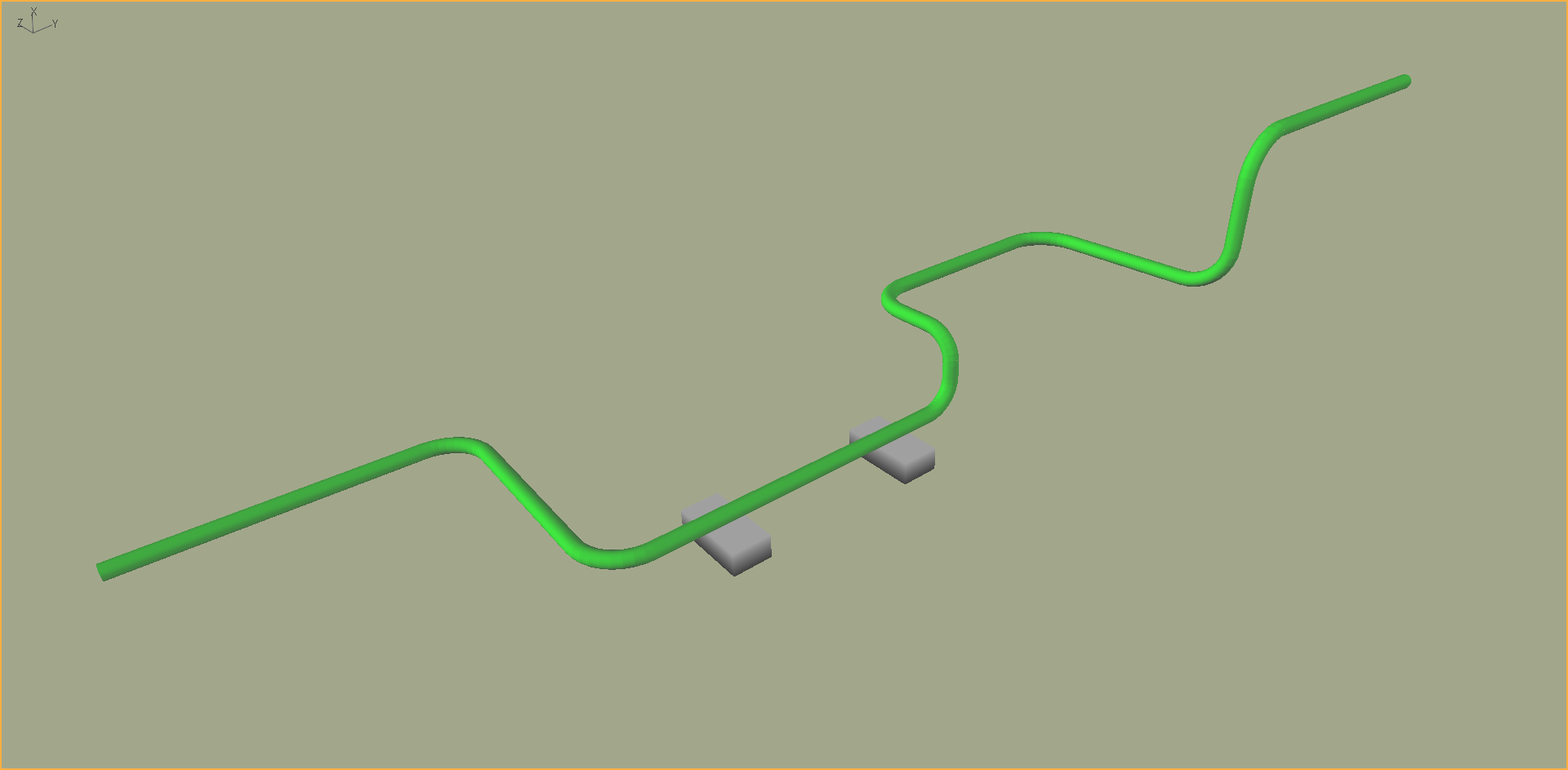
Consider the rigid spool model shown below, taken from Example G03 - Rigid Spool. As this line has quite an arbitrary shape, *LINE PATHS offers the most suitable method of model building. It could be also be modelled using a combination of *LINES (to model the straight sections), *NODE & *ELEMENT (to model the corner sections), and *EQUIVALENT (to connect the straight and corner sections together) but this would be much more cumbersome. Regardless of which modelling approach is used, the significance of the local undeformed element orientations is the same, as the line is modelled internally using a series of nodes and elements ultimately. By default, Flexcom will assign local undeformed axes to each element within the model based on the coordinates of its end nodes. This will result in a unique stress-free orientation for each element, and mean that the spool is unstressed in its as-built configuration as shown (ignoring any stresses due to self-weight or buoyancy).
In this case, you should not specify any V and W vectors, and these entries should be left blank.

Spool Model (V & W not required)
Consider the flowline model shown below, lying flat on a horizontal seabed. Similar to the spool model, it is possible to model this using *LINE PATHS, or perhaps some combination of *LINES, *NODE & *ELEMENT, but *LINE PATHS offers most modelling flexibility. By default, Flexcom will assign local undeformed axes to each element within the model based on the coordinates of its end nodes. This will result in a unique stress-free orientation for each element, and mean that the flowline is unstressed in its as-laid configuration as shown. This is obviously not ideal as in reality the flowline is only unstressed when it is laid in a straight line. In such circumstances, it is desirable to assign a common local undeformed axis system to each element in the model, so that while the flowline is restricted (via seabed friction for example) in its as-laid configuration, the required bending moment distribution is captured.
In this case, you should explicitly specify the V and W vectors. The actual values you choose are not all that important, so long as all elements in the model share a common set of vectors. Suggested values would be V = {1,0,0} and W = {0,0,1} so that the local undeformed element axes are aligned with the global axes.

Flowline Model (V & W required)
Refer to local undeformed element axes for a full discussion on the significance of undeformed element orientations in general.