Creating Customised Object Profiles |
 
|
Creating Customised Object Profiles |
|
XML (eXtensible Markup Language) is a programming language that defines a set of rules for encoding documents in a format that is both human-readable and machine-readable. Syntax recognition and error highlighting in Flexcom's keyword editor is achieved in XML for example, as the user interface understands the various keyword formats accepted by Flexcom based on pre-defined rules which have been implemented by the software developers. When defining a customised object profile for use in Flexcom, you are essentially communicating to the Model View what to display on screen, via a profile file which is written in XML format.
XML may look a little complicated to a first time user, but it is actually quite straightforward to interpret, and you will be confidently building your own profiles before long. If this is your first time working with XML, we suggest that you search for an introductory tutorial online - there is plenty of free training material and tutorial videos available.
Let's look at a sample object profile to help illustrate the use of XML. The Wellhead component provided with Flexcom (Wellhead.fcvpx) is probably the simplest one to start with. It is actually very readable as you can see. It consists of 3 separate cylinders, each defined by a central axis, a centre point, a colour, a height/length, an external diameter, and a number of segments (which defines the number of flat panels which are used to represent the cylindrical surface). Beneath the XML, you can see how the component looks in the Model View, with the wellhead component (largely grey) beneath the BOP (largely red).

XML file for Wellhead Component
 & BOP (upper) Components")
Wellhead (lower) & BOP (upper) Components
Even this very simple example illustrates a number of key features of XML...
•XML documents are composed of blocks of information known as elements. The file above has 4 elements, the wellhead, and the 3 cylinders which comprise it.
•When viewed in a compatible file viewer, XML documents are neatly coloured for ease of reading and understanding. While they can be viewed in a standard internet browser, we would recommend using a standard text editing software which supports both viewing and editing. Notepad++ is a very useful text editor which is free to download and install.
•All XML documents must have a root element. This acts as the parent element for all sub-elements which it contains. The root element in the file above, and indeed all Flexcom object profiles, is denoted by "Body".
•XML elements are created using an opening tag (the "<" symbol) followed by the element type. For example, "<Body".
•All XML elements must have a closing tag. Element definitions typically span several lines so there is a separate closing tag (e.g. "</Body>") on another line further down. Simpler element definitions may be written on a single line, but the closing tag must still be present.
•Note that XML tags are case sensitive. Opening and closing tags must be written with the same case.
•User defined properties associated with elements, known as attributes, must always be enclosed in quotation marks. For example, the name of the body ("Wellhead") and any associated properties such as dimensions, colours etc. are all enclosed in quotation marks in the image above.
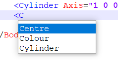
•Most text editors provide helpful tooltips while you type. The image below shows that once you add an opening tag and start typing, the editor suggests as many element or attribute types as it can.
•Indentation is highly recommended for clarity and ease of reading. Notice how the cylinder element tags above are indented by a few spaces to the right of the body element tags.
•The use of annotational comments are also highly recommended. Like everything else in XML, comments must appear in a very specific format, for example "<!-- Enter comment here -->".
•Element definitions may be shown in collapsed format for convenience if you are reading a large XML file. Simply press the minus symbol to the left of the element's opening tag. This will allow you to compress chunks of XML data so that they remain hidden from view. To expand these again later, press the plus symbol beside the opening tag.
•Note that you must adhere rigidly to the XML document rules. For example, if you forget a closing tag, the entire XML document may be rendered unreadable to the software. Advanced software developer tools known as IDEs (Integrated Development Environments) will actually highlight incorrect XML syntax. Regardless, the golden rule is to build up your syntax gradually and carefully.
Building Blocks
The wellhead profile above was created using cylinder objects only. Naturally Flexcom supports many more object types which you can use to create your customised model. Some of the more popular ones are summarised in the following table.
Object |
Description |
Attributes |
Sample Syntax |
|---|---|---|---|
Box
|
Rectangular box |
Name (text), Centre (float, 3 values), Height (float), Width (float), Breadth (float), Colour (text) |
<Box Centre="0 0 0" Height="7.1" Width="53.8" Breadth="10.6" Colour="Red"/> |
Cylinder |
Cylindrical surface |
Name (text), Centre (float, 3 values), Axis (float, 3 values). Height (float), OuterDiameter (float), InnerDiameter (float), Segments (integer), Colour (text) |
<Cylinder Name="Circle" Axis="1 0 0" Centre="0.02 0 0" Height="0.005" OuterDiameter="0.7" InnerDiameter="0.6" Segments="16"/> |
Quad |
Quadrilateral surface defined by 3 points in space |
Name (text), Positions (3 values, repeated 3 times), Colour (text) |
<Quad Colour="Black" Positions="1532.5 2273.9 -49.1,1535 2273.9 -49.1, 1535 2281.9 -49.1"/> |
Line |
Straight line between 2 points |
Name (text), Positions (3 values, repeated 2 times), Colour (text) |
<Line Positions="1538.3 2274 -20.35, 1547.3 2274 -20.35" /> |
LineMesh |
Mesh of straight lines using any number of points in space |
Name (text), Positions (3 values, repeated as many times as required), Indices (2 values, repeated as many times as required), Colour (text) Each pair of indices creates a straight line between the relevant positions. The index refers to the list order in which the points were defined (note: starting index is 0 rather than 1). |
<LineMesh Positions="1527.2 2273.9 -25 1529 2273.9 -25 1527.2 2273.9 -19.0 1529 2273.9 -19.05 1527.2 2273.9 -13.1 1529 2273.9 -13.1" Indices="0 1, 2 3, 4 5, 1 5"/> |
PolyMesh |
Mesh of triangular panels, each defined using any 3 points in space |
Name (text), Positions (3 values, repeated as many times as required), Indices (3 values, repeated as many times as required), Colour (text) Each set of 3 indices creates a triangular panel between the relevant positions. The index refers to the list order in which the points were defined (note: starting index is 0 rather than 1). Depending on the order of the indices in the triangular definition, the panel can be either forward or backward facing, based on the direction of the normal vector, and this can affect how the panels appear in the Model View. Prior to the definition of panels, you can nominate a colour which is used for all the subsequent panels, up to the next colour statement. |
<PolyMesh Name="Funnel" Colour="White" Positions="-16 13.75 -11 16 2.75 -5.5 16 2.75 5.5 -16 13.75 11 -16 -8.25 -11 16 -13.75 -5.5 -16 -8.25 11 16 -13.75 5.5" Indices="0 1 2, 0 2 3, 4 5 1, 4 1 0, 6 7 5, 6 5 4, 2 7 6, 2 6 3, 1 5 2, 2 5 7"/> |
Other possible object types include Fan, Strip, Polygon, RotationSurface, SweptSurface etc. You can also create named template objects which you can reuse multiple times (e.g. the same object could appear several times in your model view, with different dimensions and/or locations). Contact us if you are interested in further details - we can supply and describe the XSD schema which governs the XML file contents via the application of syntactical constraints.
The Translate and Rotate commands may be used to adjust the position or orientation of objects. For example, if we consider our sample basic rectangular box above...
<Body Name="Rectangular Box">
<Box Centre="0 0 0" Height="7.1" Width="53.8" Breadth="10.6" Colour="Red"/>
</Body>
We could offset it using the Translate command...
<Body Name="Rectangular Box">
<Translate Offset="20 0 0">
<Box Centre="0 0 0" Height="7.1" Width="53.8" Breadth="10.6" Colour="Red"/>
</Translate>
</Body>
Or rotate it using the Rotate command...
<Body Name="Rectangular Box">
<Rotate Angle="45" Axis="1 0 0">
<Box Centre="0 0 0" Height="7.1" Width="53.8" Breadth="10.6" Colour="Red"/>
</Rotate>
</Body>
The PolyMesh command is highly generic and very powerful - this sample helicopter profile was built using PolyMesh. If you have access to graphical building software, they typically allow export of model data in text style format (e.g. OBJ files). These files contain coordinate and connectivity data which can be readily converted it into the PolyMesh format accepted by Flexcom, including intermediary manipulating steps via Excel or NotePad++ if necessary. If you find yourself performing this operation repeatedly over time, it might be useful to create a script or macro to help automate the process. We plan to incorporate an OBJ file importer tool into a future version of Flexcom.
Model Building Suggestions
•Make sure your profile file has an .xml file extension. Object profile files in Flexcom have the file extension .fcvpx (FlexCom Vessel Profile eXtended) by default. However this file extension will not be recognised by web browsers or text editing software, so you should ensure to give your file an .xml file extension instead.
•Open your XML file in a text editor such as Notepad++, this will neatly colour code the XML syntax for ease of reading and understanding. If you have access to a software developer tool this will be even better, as it will highlight any errors in your XML syntax
•Build up your syntax gradually, taking care to adhere to the XML rules, and ensuring the integrity of your XML document.
•Link your XML file to a Flexcom model, via the *BODY,INTEGRATED or *VESSEL,INTEGRATED keywords. This will allow you to view the work-in-progress object in the Model View, giving you instantaneous visual feedback following every addition.