Getting Started |
 
|
Getting Started |
|
In order to help novice users to up-skill and improve their proficiency with Flexcom, we have compiled a series of online tutorial videos.
Model Building
Model building is very straightforward with Flexcom. Slender structures such as risers, pipelines and mooring lines may be built quickly and easily using the Lines modelling feature, while the automatic mesh-creation facility readily accommodates mesh sensitivity studies. Large floating structures (such as FPSOs, semi-subs and drill-ships) are modelled using the standard Vessel feature (displacement-driven simulation) while smaller floating structures are treated as Floating Bodies (force-driven simulation). Environmental Parameters, such as ocean depth and water density, along with a Seabed definition, typically completes the minimum required model specification.
The Model View continually updates to reflect changes to the model, and provides a preview of both the overall configuration and the distribution of finite elements.
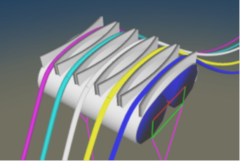
Sample Mid-Water Arch Model
Flexcom is designed to simplify the quality assurance process. The keyword style input readily lends itself to QA inspection by project managers. The integrated Keyword Editor facilitates rapid data specification, aiding the user with helpful input prompts and command auto-completion. Any inaccurate specifications are detected by automatic syntax checking and data validation. Beginner or inexperienced users may prefer to use the Table Editor. Data is entered in tabular format, with the various rows and columns clearly labelled.

Helpful Input Prompts and Automatic Data Validation
Pre-defined input Parameters form an integral part of a typical model specification. Once a parameter is altered, all dependent parameters are automatically updated, with consequent savings for model setup effort. Environmental simulation is also seamless, as one parameterised master template keyword file may be used to generate all the required input files (e.g. to accommodate a matrix of varying wave periods and headings).
Flexcom’s advanced computational technique provides supreme confidence in the engineering design. The software uses an industry-proven Finite Element Formulation, incorporating a hybrid beam-column element with fully coupled axial, bending and torque forces. Up to 10 integration points are used within each finite element to ensure a precise distribution of applied forces. Third order shape functions are used to predict solution variable (e.g. moment, curvature) variations within each element.
Flexcom uses a consistent mass formulation which integrates the mass along the length of each finite element, consistent with the fundamental principles of the finite element method, stiffness matrix assembly and shape functions. This results in a fully populated mass matrix with off-diagonal terms that include coupling terms between different degrees of freedom and different nodes, and represents a complete numerical definition of the structural mass in reality. A consistent mass definition is important for implicit time domain solvers which simulate dynamic structures, and is particularly important in accurately capturing rotational inertia effects.
Flexcom uses implicit integration to solve the equations of motions in time domain dynamics. This means that the solution at time t+Δt is based on the conditions at time t+Δt, so that the exact equations of motion are solved for at each solution time, ensuring that precise equilibrium is achieved. Explicit integration by contrast (which has never been used in Flexcom), means that the solution at time t+Δt is based on the conditions at time t, leading to the requirement for very fine time steps for solution accuracy and stability.

Advanced Computational Technique
Element forces may be presented in traditional plot format, graphically illustrated via colour contouring, or automatically collated in Microsoft Excel. These versatile post-processing options deliver tangible benefits for engineering teams, as pertinent results may be extracted quickly and easily.
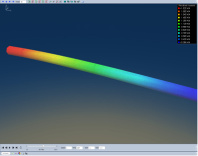
Stress Contouring
Flexcom is equipped with a fully integrated documentation system. One centralised help system encompasses all of the various sub-components, such as data inputs, background theory, and sample models. It also incorporates extensive cross-referencing for effortless browsing. The documentation is logically broken up into the following categories:
•Installation contains information on basic System Requirements and Network Licensing.
•User Interface introduces the various concepts behind Flexcom’s user interface, and software user-experience in general. It presents detailed information on the various sub-components, including the concept of a Project Workspace, Model Building (via the Keyword Editor or Table Editor), Running Analyses (explaining Analysis Jobs and Work Sequence), and Results Examination (via the powerful Model View and Plotting features).
•Flexcom's main user interface also incorporates two specific modules, Flexcom Wind and Flexcom Wave, which are specifically designed to create models for floating wind turbines and wave energy conversion devices, respectively.
•Data Inputs provides a complete reference guide to all data inputs used in Flexcom.
•Theory provides a comprehensive background on the modelling and analytical capabilities of the software. It includes a section on Flexcom’s industry-proven Finite Element Formulation, an advanced computational technique which provides supreme confidence in the engineering design. It also discusses the comprehensive range of Postprocessing options available in Flexcom.
•Examples describes a set of examples which illustrate some of the range of applications for which Flexcom may be used. Sample models cover areas such as Top Tensioned Risers, Steel Catenary Risers, Flexible Risers, Mooring Systems, Offloading Systems, Pipelines, Hybrid Riser Systems and Installation Analysis.
•References lists all the technical publications referenced throughout the help system.
In addition to the comprehensive documentation we also host an online Knowledge Base for Flexcom as well as all of Wood Group desktop software products.
This web based resource contains answers to frequently asked questions on the use of our products. It essentially provides best practice advice on how to use the products and troubleshoot potential issues encountered.
Content is continually added to the Knowledge Base over time and so it represents a valuable reference for engineers who are actively using our software.
To access the Knowledge Base users are asked to register, via the link, with their company email address and individual password. We will approve new users as soon as possible after registration.
Once access has been granted, users are then free to navigate through all the provided content, search for answers on a particular topic, and vote on the most helpful answers.