Computational Methodology |
 
|
Computational Methodology |
|
This section outlines the computation methodology for floating offshore wind turbines. Further information is provided in Software Architecture, Software Couplings and Rotor Blade Model.
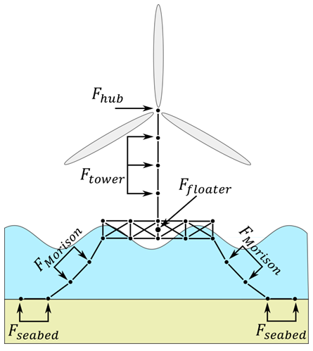
There are three primary load components in a Flexcom wind turbine simulation:
•Aerodynamic loads on the turbine blades and supporting tower
•Hydrodynamic loads on the floating platform
•Structural and hydrodynamic loads imparted by the mooring lines
Primary Load Components
Flexcom facilitates the use of the OpenFAST module InflowWind, via the *INFLOWWIND keyword, so dynamic and turbulent wind loading can be specified on the wind turbine. InflowWind processes wind inflow and supports several wind file formats including uniform, binary TurbSim full-field, binary Bladed-style full-field and HAWC formatted binary full-field wind files. It also has it's own internal calculated steady wind and supports arbitrary wind directions. Platt et al. (2016). The turbulent wind field definition is typically generated in advance using TurbSim - refer to TurbSim Overview for further information.
At each timestep, InflowWind is given the blade and tower nodal locations and then calculates the undisturbed wind-inflow velocities at these positions. As described in Platt et al. (2016) - "There are no states in the module: each wind velocity component is calculated as a function of the input coordinate positions and internal time-varying parameters, undisturbed from interaction with the wind turbine. For full-field wind data types, InflowWind uses Taylor’s frozen turbulence hypothesis—valid only for stationary conditions—to translate wind defined in two dimensional planes into three spatial dimensions, using the mean wind speed as the advection speed".
Aerodynamic loads on the blades and tower are computed directly by AeroDyn. The aerodynamic calculations are based on the principles of actuator lines, where the three-dimensional (3D) flow around a body is approximated by local two-dimensional (2D) flow at cross sections, and the distributed pressure and shear stresses are approximated by lift forces, drag forces, and pitching moments lumped at a node in a 2D cross section. Analysis nodes in AeroDyn are distributed along the length of each blade, the 2D forces and moment at each node are computed as distributed loads per unit length, and the total 3D aerodynamic loads are found by integrating the 2D distributed loads along the length. The loads on the rotating blades are then passed to the Flexcom solver for input into the global force vector on the right hand side of the equations of motion.
The wind load on the tower is based directly on the tower diameter and drag coefficient and the local relative wind velocity between the freestream (undisturbed) wind and structure at each tower analysis node in AeroDyn. These loads are then passed to Flexcom, where they are applied to the corresponding tower node in the structural model, and the global force vector is augmented accordingly.
Further information is available in:
•Turbine Geometry & Aerodynamic Coordinate Systems
Hydrodynamic loading on the floating platform includes the various items listed below. The loads are computed for the floating body as a whole, and then applied at an appropriate location in the global force vector (e.g. at a node which corresponds to a centralised location such as the centre of gravity).
•First-Order Wave Loads (high frequency) derived from Force RAOs
•Wave Radiation Loads. An important issue arises with respect to the Added Mass and Radiation Damping terms associated with the floating body, and how these are modelled in the time domain. The frequency-dependent nature of these terms is accounted for using the established impulse response approach developed by Cummins (1962), and its implementation in Flexcom is described in detail by Connaire et al. (2003) and Lang et al. (2005). Specifically, the frequency-dependent damping term is replaced by a convolution integral of retardation functions and velocity time histories in the time domain.
•Viscous Damping Loads. These may be derived from centralised Viscous Damping Coefficients at some point on the floating body, or simulated in a distributed manner via Morison's Equation.
•Second-Order Wave Drift Loads (low frequency) derived from Quadratic Transfer Functions (QTFs)
•Current Loads computed via Current Coefficients
•Wind Loads computed via Wind Coefficients
•Hydrodynamic Loads determined according to the theory of manoeuvrability
Further information is also provided in these related articles...
•Diffraction-Radiation Theory & Morison's Equation discusses the main differences between these hydrodynamic modelling approaches.
•Floating Body Modelling Detail discusses relatively simple (concentrated loads) and more complex approaches (distributed loads) for physically modelling the floating structure.
Mooring lines are modelled in the standard fashion using beam elements. These elements form a natural part of the overall finite element solution, so their effect on the floater is handled automatically. Specifically, effective tensions in the mooring lines induce point loads on the floater at the fairlead connection points. In addition to the axial loads, mooring lines are subject to self-weight and Buoyancy Forces. Hydrodynamic Loading is based on Morison’s Equation, including the fundamental components of drag, added mass and hydrodynamic inertia. Contact algorithms are used to simulate Seabed Interaction with the local seabed topography.