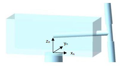
This section provides a series of schematics which graphically illustrate the various coordinate systems used for wind turbine modelling. Refer also to Turbine Geometry for additional information.
All of the images are reproduced from NREL's AeroDyn program documentation, with the kind permission of NREL.
This coordinate system translates and rotates with the top of the tower, plus it yaws with the nacelle.
•Origin A point on the yaw axis at a height of 'TowerHt' above mean sea level. Refer to Conventional Upwind Turbine Layout for an illustration of TowerHt.
•xn axis Pointing horizontally toward the nominally downwind end of the nacelle
•yn axis Pointing to the left when looking toward the nominally downwind end of the nacelle
•zn axis Coaxial with the tower/yaw axis and pointing up

Nacelle/Yaw Coordinate System

AeroDyn Local Blade Coordinate System (Looking Toward the Tip, from the Root) – l: Lift, d: Drag, m: Pitching, x: Normal (to Plane), y: Tangential (to Plane), n: Normal (to Chord), and t: Tangential (to Chord)
(image courtesy of NREL)