This section provides a series of schematics which graphically illustrate the various sub-components of a wind turbine. It serves as a useful reference point for all information relating to turbine geometry. Refer also to Aerodynamic Coordinate Systems for additional information.
All of the images are reproduced from NREL's AeroDyn program documentation, with the kind permission of NREL.
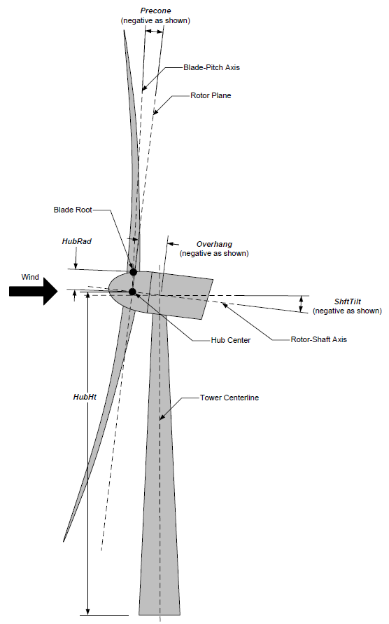
AeroDyn Driver Turbine Geometry
(image courtesy of NREL)
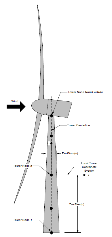
AeroDyn Tower Geometry
(image courtesy of NREL)
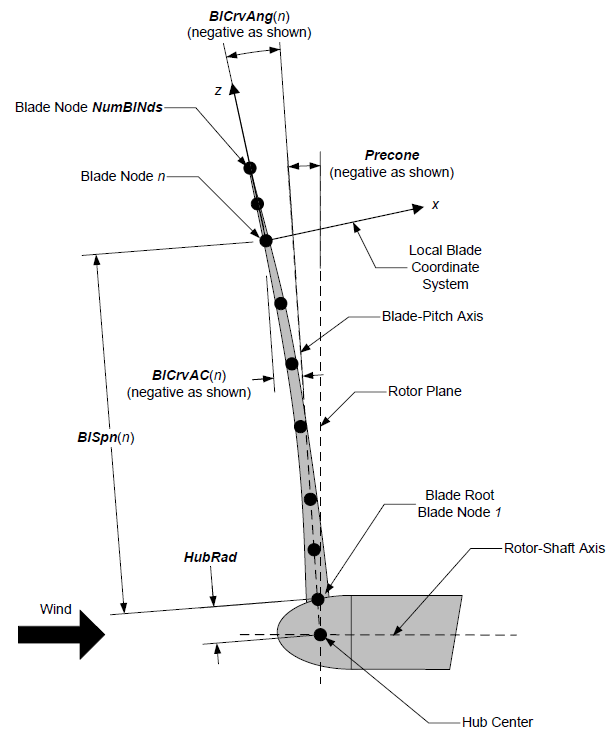
AeroDyn Blade Geometry - Side View
(image courtesy of NREL)
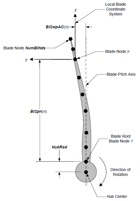
AeroDyn Blade Geometry - Front View (Looking Downwind)
(image courtesy of NREL)
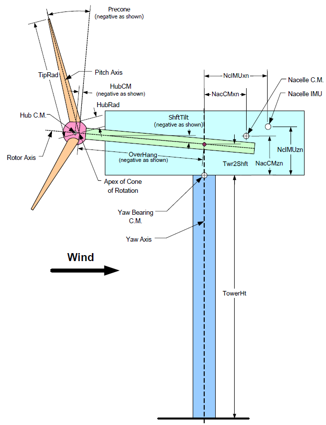
Layout of a conventional, upwind, 3-bladed turbine
(image courtesy of NREL)