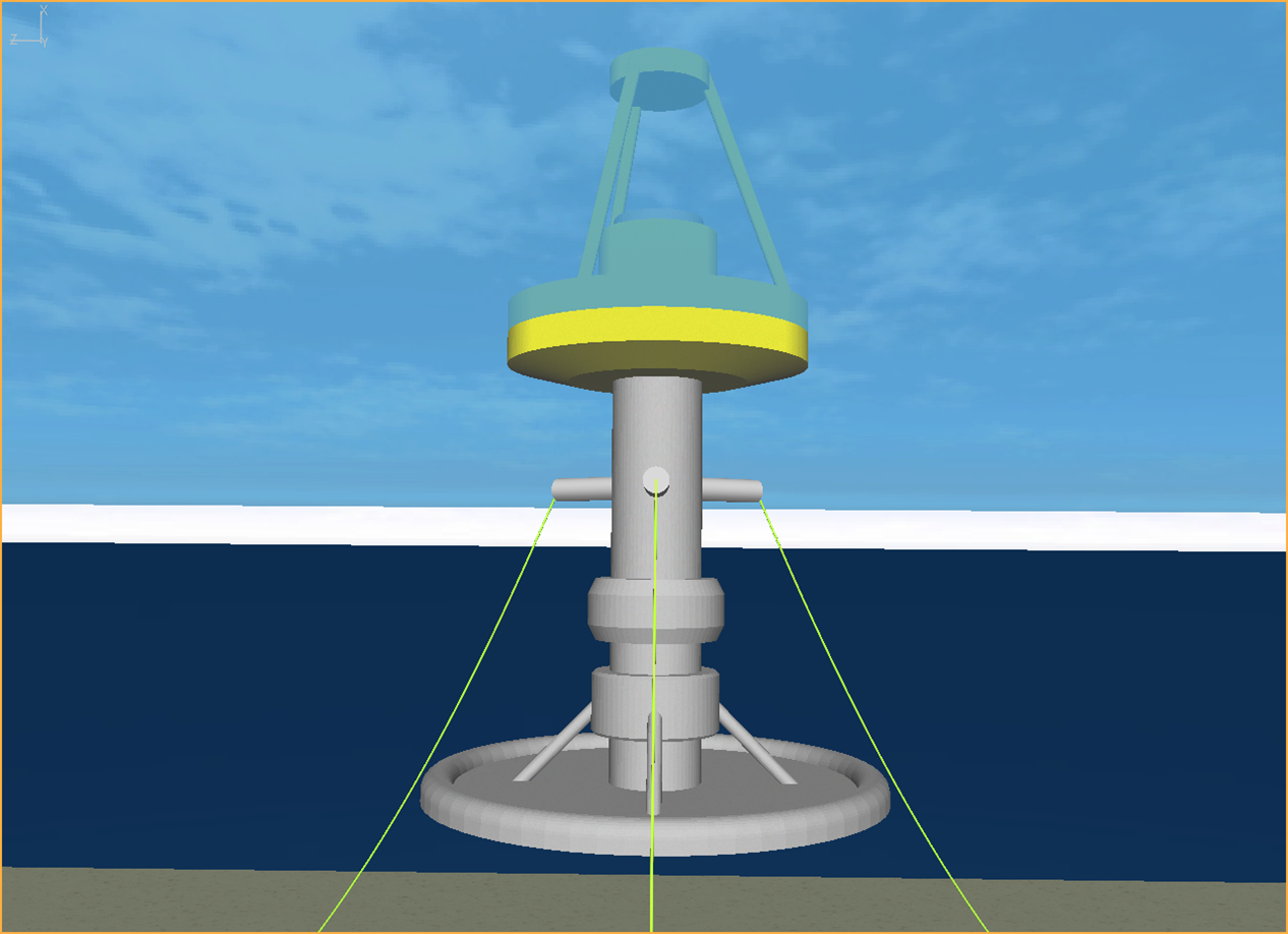
The Flexcom model of the wave energy converter is shown below.

Flexcom model of Floating Point Absorber
Both the surface float and the spar buoy are modelled using a straight Line along their respective central axes. Line Locations are used to position finite element nodes at the respective centres of gravity. On the spar buoy, a line location point is also defined to identify the vertical elevation of the mooring connections. Each line is assigned rigid Stiffness terms as the individual components are assumed to act as rigid bodies. Each line is assigned a Mass per Unit Length of zero (as the total mass is concentrated at the centre of mass), a Buoyancy Diameter of zero (as the total buoyancy is concentrated at the centre of buoyancy), and a Drag Diameter of zero (to suppress the application of Morison drag loads).
An individual Floating Body is defined for both the surface float and the spar buoy, to model its hydrodynamic characteristics. Inertia terms are specified at the floating body centre of gravity. Hydrostatic Stiffness terms are used to simulate restoring forces and moments due to buoyancy. Added Mass, Radiation Damping and Force RAO coefficients are defined over a range of discrete frequencies - these terms enable the computation of incident, diffracted and radiated (linear) wave potentials to be simulated. Note that these inputs are derived separately from a radiation-diffraction analysis.
3 short Lines are used to create fairlead connections for the mooring lines, providing a radial separation of 3m (corresponding to the spar diameter) between the spar elements and the mooring connection points. The fairlead connections are assigned large Stiffness terms to simulate rigidity, and a Mass per Unit Length of zero. They are not intended to induce any hydrodynamic loading, so they are are assigned zero values of Buoyancy Diameter and Drag Diameter. Equivalent Nodes are used to attach the fairlead elements to the spar elements.
The mooring lines are created using 3 separate Lines. The upper end of each mooring line is attached to the relevant fairlead node on the spar buoy using a Hinge Element, while the lower ends are constrained using Fixed Boundary Conditions. Realistic Stiffness, Mass per Unit Length, Buoyancy Diameter and Drag Diameter terms are assigned to the mooring lines.
Power Take-Off
The power take-off mechanism is modelled using a Damper Element and a Spring Element in parallel. Both elements run between the respective centres of gravity of the surface float and the spar buoy. The damper provides a linear resistance which is proportional to the rate of expansion or contraction of the power take-off. In regions of free movement the spring element provides a low restoring force. If the mechanism approaches its end stops, the spring stiffness is increased to provide a high level of resistance to any further motion.