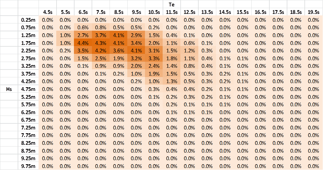
The wave energy converter was designed for a reference site located offshore of Eureka in Humboldt County, California. This particular location was identified by the U.S. Department of Energy as it has a wave climate representative of the US’s west coast, and moreover a wide range of high-fidelity oceanographic data sets is readily available for this area. A wave scatter diagram for the reference site is presented below (Neary et al., 2014).

Wave Scatter Diagram for Eureka Site (Neary et al., 2014)
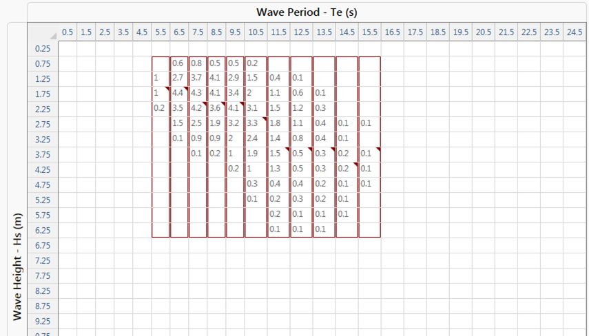
Numerical simulation of an entire scatter diagram in the time domain can be quite computationally expensive, so the Summary Wave Scatter feature offers an economical extrapolation technique with a view to estimating the full results matrix based on a selection of ‘reference seastates’ within the scatter diagram. The scatter diagram is first sub-divided into ‘blocks’, where similar seastates are grouped together, before a single seastate is nominated as being representative for each block. Based on the numerical simulation results for the reference seastate within each block, the program fabricates a Summary Database File for each of the remaining cells within the block. This allows Summary Postprocessing Collation to be used as normal to collate results from all seastates.

Nomination of Seastate Blocks and Reference Seastates
The wave scatter diagram contains a total of 84 different seastates with non-zero percentage occurrences, spanning across 11 different periods and 12 different wave heights. For computational efficiency, the scatter diagram is sub-divided into 11 blocks as shown above, with one block for each different wave period, and a sample wave height selected as the reference seastate within each block.
Numerical Parameters are defined to represent significant wave height (Hs) and wave energy period (Te), and Keyword Based Variations are used to define values of Hs and Te appropriate to each individual simulation. The *COMBINATIONS keyword is used to generate the required input files based on the master template file, and neatly names each file based on the Hs and Te values. Given that Flexcom has traditionally modelled wave spectra in terms of either Tz or Tp, the Te values are converted to Tp before being used to define the Jonswap spectrum in Flexcom. Refer to Wave Energy Period for further information on the conversion process.
After the dynamic simulations for the 11 reference seastates have been completed, the Summary Wave Scatter feature is used to fabricate Summary Database Files for all the non-reference seastates in the wave scatter diagram. The Summary Postprocessing Collation feature is then used to create 3D plots of electrical power, mooring fairlead tensions and mooring anchor loads.