Damper Elements |
 
|
Damper Elements |
|
Damper or dashpot elements can be used to directly model local damping effects. Example applications would be in the analysis of a drilling riser model that includes a crown heave motion compensator, or the damping of SCR motions by soil in the touchdown zone. The damper element is completely defined by its damping coefficients (constant, linear and quadratic options are available), and there are no associated mass or stiffness inputs.
Damper elements can be applied in a translational or rotational context.
Note that damper elements are fully-fledged elements of the finite element model, whose geometry (nodal coordinates and connectivity) must be defined in any of the standard ways.
The axial force exerted by a translational damper element, F, is defined as follows:
![]() (1)
(1)
where ![]() is the relative velocity between the element end nodes in the axial direction of the element, F0 is the constant damping force, and C1 & C2 are the linear and quadratic damping coefficients respectively. Each component term may be specified as a single (constant) value, or as a series of values which depend on time or velocity. F0, C1 & C2 can each vary as a function of time, and C1 can also vary as a function of velocity.
is the relative velocity between the element end nodes in the axial direction of the element, F0 is the constant damping force, and C1 & C2 are the linear and quadratic damping coefficients respectively. Each component term may be specified as a single (constant) value, or as a series of values which depend on time or velocity. F0, C1 & C2 can each vary as a function of time, and C1 can also vary as a function of velocity.
It is possible to control the application of the constant damping force (F0 term) by specifying a velocity threshold. By default no ramping is applied, so the damping force is applied in full at all times. The significance of the velocity threshold is illustrated in the figure below. Rather than switching instantaneously between positive and negative force values, the constant force term is gradually ramped up over a finite range of relative velocity. This tends to smooth out the applied damping forces and eliminates the possibility of a dramatic alternation between positive and negative force terms for small extensions and contractions of the damper element.
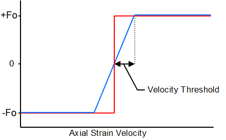
Velocity Threshold
Damper elements are sometimes used to simulate power extraction. In this context, Flexcom provides post-processing options for damper power. The power produced in each damper element is calculated as follows:
![]() (2)
(2)
See the Force Variable Input section for details on how to output damper power.
For rotational damper elements, the moment exerted by the element, M, is defined as follows:
![]() (3)
(3)
where ![]() is the relative rotational velocity between the element end nodes and C1 is the linear damping coefficient.
is the relative rotational velocity between the element end nodes and C1 is the linear damping coefficient.
•*DAMPER is used to define damper elements.
•*DAMPER DATA is used to define coefficients for use with damper elements.
If you would like to see an example of how these keywords are used in practice, refer to A01 - Deepwater Drilling Riser.