Compression and Buckling |
 
|
Compression and Buckling |
|
There are two main types of element of Flexcom (ignoring Special Elements such as hinges, springs, dampers, winches etc.):
•14-DOF beam element with fully coupled axial, bending and torque forces
•7-DOF truss element which has no structural resistance to bending or torsion
Compression and buckling are handled differently by these element types so a separate discussion is included on each.
Flexcom is capable of modelling buckling of a line section under compressive axial loads, provided that the relevant beam element lengths and the solution time-step are sufficiently refined. With regards to the element length, the critical Euler load is an important parameter. This is defined as the maximum compressive load which a beam can sustain without buckling laterally.
The critical Euler load in a beam element is defined as:
 (1)
(1)
where:
•FEuler is the critical Euler load
•EI is the bending stiffness
•L is the element length
Flexcom will issue a warning if the compressive load experienced in any given beam element exceeds the critical Euler load. Where this occurs, you are advised to use a refined mesh density in the region where the excessive compression is being experienced (the warning message will direct you to the relevant element number, and if you have built your model using lines, the line section in which it is located). You are free to ignore the warning message, but in doing so you accept the risk that the model is not sufficiently refined to accurately capture the localised buckling. By default, the critical load is defined by the formula above, but you can explicitly specify a different limit if you wish. It is also possible to suppress the warning messages completely, should you decide that (i) you are happy with the model definition and/or (ii) that the Euler limit is exceeded occasionally during a simulation rather than regularly.
A truss element has zero structural bending stiffness, so in theory it has no resistance to bending and is incapable of supporting any compressive load no matter how small. However, a numerical solver such as Flexcom can predict effective compression in certain circumstances. It is important to note that bending stiffness is not solely limited to structural properties, and resistance to bending can also come from several other sources:
•The truss element formulation includes a geometric stiffness term when the element is in tension. Although this stiffness contribution should be inactive when a truss element goes into compression, it is possible that adjacent elements may still be in tension, particularly in models which are subjected to strong and rapidly changing dynamic excitation.
•A truss element experiences drag and inertial loads the same way as a beam does. These loads can inhibit the ability of a truss element to move laterally with respect to adjacent elements, particularly if the structural velocities and accelerations are significant. Buoyancy forces can also have a similar effect albeit less significant.
•Bending stiffness may be provided by a supporting structure, such as seabed contact or guide surface contact.
•Local frictional effects related to contact can provide additional resistance to perpendicular movement of a truss element.
Consider a simple catenary mooring chain which is attached to a vessel experiencing severe wave loading. The vessel will heave and pitch in accordance with the vessel RAO definitions in a decoupled analysis, or be subjected to hydrodynamic loads in a coupled analysis which induce vessel motions. During the downward stroke, the movement of the fairlead forces the mooring line downwards. Resistance in the water column is relatively low, comprising largely of axial drag forces on the line, so that much of the resistance to the mooring line inertia occurs close to the seabed. In the real world, the mooring chain will naturally collapse in this region. In the numerical environment of Flexcom, successive elements should move in different directions to reflect the local buckling. Because the mooring chain can adopt an almost infinite number of configurations on the seabed, the numerical solver is not solving for the exact configuration (which would be an indeterminate problem) but rather a representative solution. The local buckling details are immaterial as the only variable of interest is mooring line tension, but the key point is that the mathematical model is not necessarily an exact representation of the physical scenario. Intuitively one would expect that a truss element should never experience effective compression, but it is mathematically possible in a numerical model. Small values of compression may usually be ignored, but significant compression is possible given the sensitive nature of this issue.
Flexcom will automatically issue a warning message if compression is experienced by a structure which is modelled using truss elements. This message contains information regarding:
•The element set in which the compression occurs.
•The maximum amount of effective compression which is experienced over the course of the simulation.
•The element number which corresponds to the maximum value.
•The length along the element set where this element is located. This is typically located in the touchdown zone.
•The first element of the set which experiences any compressive loading. If compression occurs in the touchdown zone, some level of compression may extend all the way to the anchor point, particularly if a smooth seabed is used.
•The last element of the set which experiences any compressive loading. This is usually located in the water column, but compression can potentially extend up towards the fairlead point.
•The total length of line which experiences effective compression at any point during the simulation. This is the difference between the lengths of the first and last elements respectively along the element set.
You could also request an envelope plot of effective tension using the Database Postprocessor for a graphical overview of the extent of the compression.
There are several options available to you if compression in truss elements is posing problems.
•Damping. Applying some level of stiffness proportional damping to the truss element set is generally recommended. This can greatly reduce the effects of high frequency noise in the numerical solution. However, it does not fully address the fundamental problem of converged solutions which include compression in truss elements.
•Mesh Refinement. Experience suggests that this is a critical modelling aspect - having a sufficiently refined finite element mesh is key to the elimination of compression. Shorter elements afford the numerical solver with greater opportunity for allowing adjacent truss elements to displace laterally with respect to each other. However, this solution comes at the expense of larger models and slower run times. It is important to note that the full structure does not need to be remeshed, and detailed refinement of a carefully selected sub-section centred around the location of maximum compression is recommended. The most critical location is obvious from the warning message and mesh refinement is very easy if your model is built using the *LINES keyword.
•Time Stepping. Time step size does not appear to have a major impact in this area. In fact, noisy solutions are sometimes exacerbated by the use of smaller time steps. However, every model is different and a quick sensitivity study on time step size could yield positive results for very little effort.
•3D Loading. If the model and applied loading is contained within a particular plane such as the global XY plane, then the solution is effectively a 2D one. Compression is avoided when truss elements move laterally with respect to each other (laterally in this context means perpendicular to the truss element's primary axis which runs from start node to end node). If there is no out-of-plane loading present, there is no incentive for any of the truss nodes to move out of plane. This is a quirk of the mathematical solver which can be readily avoided by including some additional loading. For example, if the simulation contains wave loading which is aligned with the plane of the model, you could include a small amount of current loading in the perpendicular direction. If the model already contains both wave and current loading, then you could introduce a slight separation between the wave and current directions, one acting slightly to the left in plan view and the other acting slightly to the right.
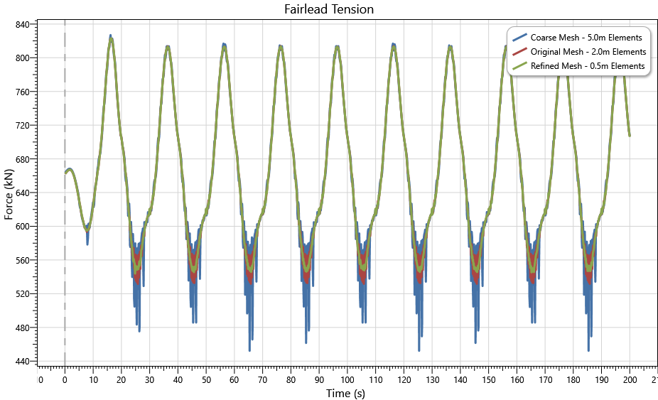
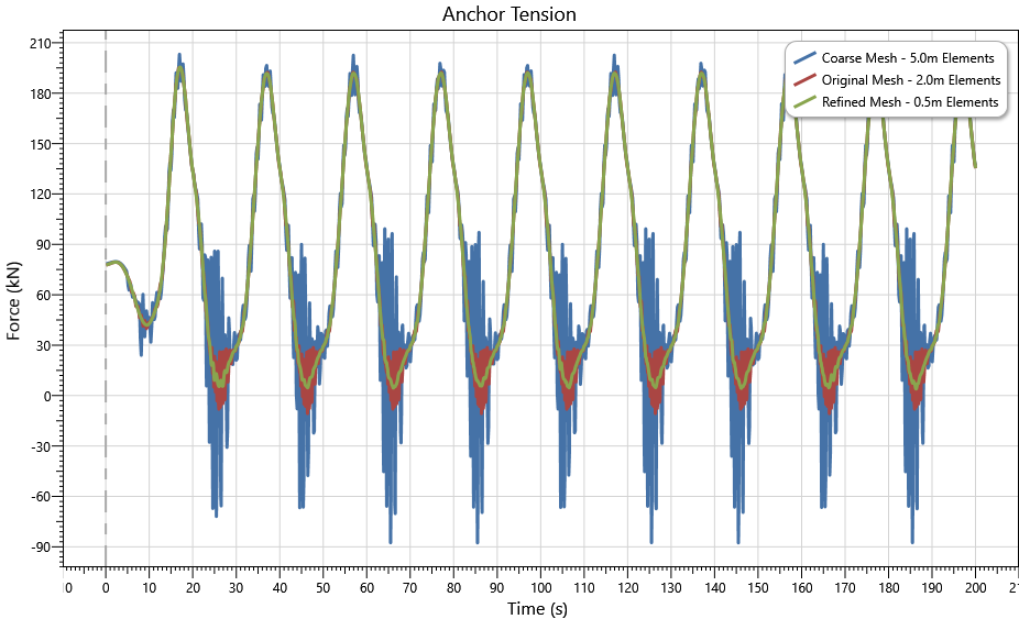
This hypothetical example illustrates the benefits of mesh refinement. The model was specifically created to demonstrate the issue of compression in truss elements. It is a simple catenary mooring line (375m long) in relatively shallow water (100m). The chain is heavy (685kg/m) and has a high extensional stiffness (3270MN). The vertical section of the line is quite steep (just 38m layback/horizontal separation between the fairlead and the touchdown point). This serves to lower the static pre-tension in the line and render it more susceptible to going slack when dynamic excitation is applied. A smooth flat elastic seabed is used. Out of plane current loading is applied (0.4m/s, uniform with depth). Sizeable vessel motions (10m heave and 5m surge) are applied to the fairlead in a dynamic simulation which is run for 10 periods, with the prescribed motions ramped up over the first period. A small amount of damping (coefficient = 0.05) is included to help reduce any high frequency noise.
The following table and accompanying figures present some key findings from the finite element mesh sensitivity study.
Parameter |
Base Case |
Refined Mesh |
Coarse Mesh |
|---|---|---|---|
Element Length |
2.0m |
0.5m |
5.0m |
Number of Elements |
187 |
632 |
75 |
Run Time |
12s |
52s |
5s |
Minimum Anchor Tension |
-10.7kN |
4.0kN |
-87.5kN |
Length of line experiencing compression |
278.7m |
7.5m |
290.0m |
Maximum Fairlead Tension |
813.9kN |
813.3kN |
816.9kN |
Some observations are as follows:
•Refining the mesh density reduces the amount of effective compression in the mooring line.
•Maximum fairlead tensions are practically independent of the mesh density used i.e. the presence of effective compression in the seabed or touchdown regions is immaterial.
•Refining the mesh density creates a computational overhead which may not be justified. However, the trends may be case specific so users are advised to perform sensitivity studies using their own custom models.
•*GEOMETRIC SETS is used to assign geometric properties to element sets, and includes an option to set or disable the Euler compression check for beam elements.
•Example C01 - Free Hanging Catenary considers a flexible catenary riser which experiences compression in the touchdown zone. This example is based on a publication by McCann et al., (2003).
•Example F02 - Upheaval Buckling simulates a subsea pipeline which experiences compressive axial loads leading to upheaval buckling.
•As part of their studies, O’Brien et al., (2003) consider the prediction of buckling onset and subsequent post-buckling response of an elastic column.