Contact Modelling |
 
|
Contact Modelling |
|
Theoretical Contact Model
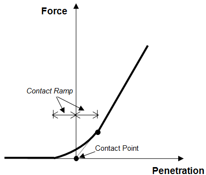
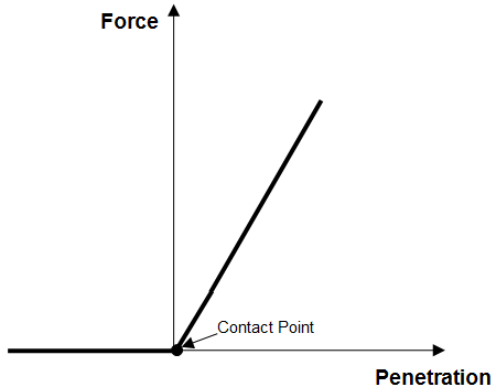
Non-Linear Contact Model
In the second figure above, rather than the contact spring stiffness being activated suddenly when contact occurs, the force in the spring is gradually ‘ramped up’. This means that there is some force in the spring before a node penetrates the guide surface, but the magnitude is relatively small. Overall, the contact algorithm provides a robust and accurate engineering approximation. The distance over which the force in the spring is ramped up is symmetric about the Force axis. In other words, the distance from the start of the ramp to the Force axis is the same as the distance from the Force axis to where the ramp meets the linear surface stiffness curve. In Flexcom, these equal distances define an input called the Contact Ramp. This input assumes a value of zero by default, meaning that the spring force-deflection characteristics are as shown in the first figure above. It is difficult to provide meaningful guidance as to what Contact Ramp might represent a “reasonable” value, but a distance of 0.1m (or equivalent in Imperial units) is tentatively suggested as a starting point if you are unsure.
It is also worth noting that the curve used to gradually ramp up the force in the contact spring is governed by a power law equation and the associated ‘power’ value can be specified through the Exponent input in the contact modelling settings. The default value for this input is 1.5, which probably represents an optimum value. However for high stiffness supports you may wish to reduce the Contact Power to a smaller value (e.g. 1.0). Reducing the power has the effect of reducing curvature in the ramp region.
•*CONTACT MODELLING is used to specify specialised parameters relating to guide surface contact modelling.