Slug Flow |
 
|
Slug Flow |
|
Slug flow is very complex in reality, with slugs lengthening and contracting, accelerating and decelerating, overtaking, merging, separating etc. General practice in industry is to adopt to simplified modelling approach which offers a compromise solution balancing accuracy and complexity alongside feasibility and data availability. Hence an ‘idealised slug flow' model is often used, which represents slug flow as a moving ‘train’ of alternating liquid slug and pocket components with each component characterised by an equivalent density and velocity (Kavanagh et al., 2013).
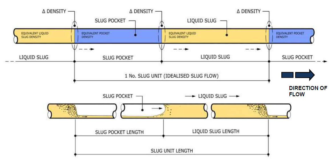
Idealised Slug Flow (Kavanagh et al., 2013)
A ‘train’ in this context means a series of slug units being passed through a piping system. Slug trains may be regular or irregular.
•In regular train analyses, the same slug type is repeatedly passed through the system until a steady state response is achieved.
•In an irregular train analysis, different slug types are passed through the system.
Regardless of slug type (e.g. single unit, regular train or irregular train), either a fixed or variable slug unit can be used.
•Fixed units are assumed to not change properties as they pass through the system.
•Variable slug units have global properties that vary with time as they pass through e.g. the slug units can accelerate, decelerate, elongate, contract.
While all scenarios noted above may be handled by Flexcom, typical engineering practice in industry appears to be the modelling of flow conditions in terms of irregular/fixed slugs. Firstly this involves the use of flow simulation software such as OLGA to produce an arbitrary time history of slug profile. Next the time history can then be transformed into a series of harmonics, based on a statistical representation of the flow regime. Each harmonic represents a certain portion of the slug spectrum, and a large number of slug harmonics may be contained in a single Flexcom simulation. While the raw data from a flow simulation program could be used to define an arbitrary time history of irregular/variable slugs explicitly in Flexcom, this approach is generally not adopted due to statistical uncertainty (the simulation would need to be extremely long, and/or many variations/windows would need to be simulated). Even with the irregular/fixed approach, multiple time domain representations (where the sequence of the various harmonics is different in each) are recommended in order to check sensitivity.
It is important to note that Flexcom is not capable of predicting fluid flow itself – it relies on flow simulation software for this information – rather it models the structural loads induced by the moving slugs.
All slug related data is specified via the *SLUGS keyword, which is supported by the *INTERNAL FLUID keyword.
The governing properties for a slug are its length, density, velocity, the element set to which it applies, and the start time at which the slug enters the first element in the set. For slugs of constant properties, the slug velocity is an optional input, and by default the slug is assumed to move with the same velocity as the entraining fluid. Time varying slugs facilitate a more realistic slug flow definition, more complex than idealised slugs of constant velocity and density. In this case, the inputs include velocity and density at the slug head and tail respectively as a function of time. Slugs may be single or periodic. If a series of slugs is being considered, the number of slugs must be specified, along with a time delay between the entry time of each slug to the first element of the set. Refer to *SLUGS for more details regarding the specification of inputs.
Slug flow affects the various load terms induced by internal fluid, including Gravitational and Inertial Forces, Centrifugal Forces, Coriolis Force, Hydrostatic Pressure and Dynamic Pressure. You are invited to read these related articles for further background reading.
The position of each slug is monitored throughout an analysis and affected elements are identified and loaded accordingly.
Partial filling of an element with a slug may also be captured. For any element which is either partially or wholly filled with a slug, the number of integration points for that particular element is temporarily increased to the maximum number (which is equal to 10, assuming the user is not already using this number). The composition of the internal fluid is then determined on an integration point-by-point basis – each integration point is assumed to govern a section of the element in the region of that point. This ensures that the composition of the entrained fluid is accurately quantified, and means that relatively long elements may still be used without compromising the accuracy of the slug flow model.
It is possible to assign several different slugs to any given element set, and each ‘master’ slug may have a number of related ‘follower’ slugs. There may be several ‘master’ slugs, each of which will have different start times, and possibly different velocities also. It is also possible to combine both constant and time-varying slugs in the same analysis. Slugs can potentially elongate and contract over the course of an analysis, given that slug head and tail velocity may be specified as a function of time. In this context it is important to note that any given location in the model can only be assigned a single slug type at any instant in time. If two or more conflicting definitions occur, then the program will simply assume that the latest slug definition takes precedence over earlier slugs. ‘Latest’ in this respect means the last relevant entry in the keyword file. In reality, slug flow is a complex phenomenon, and slugs can conceivably dissolve into, merge with or supersede other slugs. So it is possible that slugs may be defined to deliberately overlap with each other. However, inadvertent overlapping due to erroneous data specification cannot be detected by the program, so the onus is on the user to ensure the integrity of the input data.
Flexcom visually displays slugs in the structural animation, which provides a very helpful means of visualising the slug flow post-simulation. The image below shows a portion of a rigid spool (shown in green) with two different slugs flowing through it (the main slug body is shown in dark red, with the tail portion shown in brighter red). Flexcom uses a series of auxiliary elements which track the slugs, highlighting whole or partial elements which contain slug material. If you do not see slugs in your structural animation, you should ensure that the Slug Display option is set to Yes (the default setting) before running your simulation, and that auxiliary element sets are enabled in the model view.

Slug Display
Although visualisation is an integral part of understanding slug induced loads, the use of auxiliary elements does result in increased database file sizes, which take up more disk space, and may also have some impact on simulation and post-processing times. For maximum efficiency, some users prefer to set the Slug Display option to No, and switch it on occasionally, for example to visually inspect slug paths during critical load cases only.
Purely from a display perspective, all elements in the model could be filled with every slug defined if (i) all slugs were long enough to span the entire model and (ii) all slugs were overlapping each other. In reality, only one slug may be present at any given location, and this is reflected by the numerical model whereby the most recent slug definition takes priority at locations where slug overlapping occurs. But the display feature does not operate this way, and will create display elements for all slugs regardless of precedence. So the maximum number of display elements is set equal to the number of elements times the number of slugs. This amount of elements is conservative and highly unlikely to be ever required in practice. Hence there is also a user-defined option to manually choose the required number of display elements, thereby overriding the default value.
•*SLUGS is used to specify parameters relating to slug flow.
•*INTERNAL FLUID is used to define the properties of an internal fluid.
•*PRINT is used to request additional printed output to the main output file. Specifically, the OUTPUT=SLUG FLOW option is used to request additional data pertaining to fluid/slug flow.
If you would like to see an example of how these keywords are used in practice, refer to G03 - Rigid Spool. For a very quick overview, watch our Rigid Spool video online.