Mixing Cable and Rigid Elements |
 
|
Mixing Cable and Rigid Elements |
|
One situation where it is necessary to consider carefully the undeformed orientation of cables is where a structure combines elements that are defined on a cable or cables (we call these cable elements for convenience), and elements that are not defined on a cable. For convenience, we term the latter rigid elements, although this is certainly not intended to suggest they cannot be, for example, sections of flexible riser.
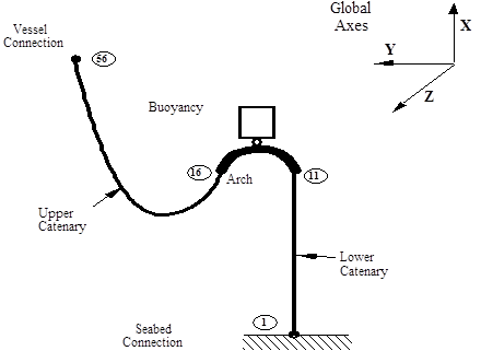
An example is again useful in illustrating the principles involved. The diagram below shows a certain type of Steep-S Flexible Riser. A lower catenary section extends from the seabed to a rigid arch or ‘gooseneck’. A longer upper catenary extends from the gooseneck to the vessel connection point. A buoyancy module is connected to the arch by means of a hinge or flex joint, but the modelling of this part of the structure is of no consequence to the discussion to follow and so is omitted for clarity.
In developing a Flexcom model of this system, a cable would normally be used only for the upper catenary section. The lower catenary would typically be specified as initially vertical. The gooseneck would be modelled using, say, 5 elements with coordinates directly specified (these elements are undeformed in the curved shape below). So the model would contain one cable only between, say, Nodes 16 and 56. (This would be the case whether or not you used lines to define this model, an application for which they would be ideally suited, or you defined the geometry yourself explicitly).
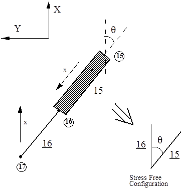
It is important to understand what happens if you do not explicitly define the undeformed orientation of the elements on this cable. The following diagram shows the situation at Node 16. The local undeformed axes of Element 15 are evaluated using the program default algorithm based on the nodal coordinates. The local x axis only is shown for convenience, pointing from the first node of the element (15) to the second (16). On the other hand, the program default algorithm for cable elements defines the local undeformed axes for Element 16. The local x axis in this case is vertical. What this means is that the stress free structure configuration is assumed to have a bend or kink at Node 16, which will result in large restoring forces being induced as the structure takes up its static configuration. This is obviously incorrect.
Situation at Node 16
The answer lies in associating the undeformed orientation of Element 15 with all of the Elements 16 to 55. This will mean both that the undeformed structure will not have a kink at Node 16, and equally that the undeformed orientation of the cable of the upper catenary will be with the riser stretched out in a straight line as required. With this in mind, the following are the steps for defining a typical finite element geometry for the structure. Nodes 1, 11 to 16, and 56 are defined explicitly in terms of coordinates. Nodes are generated between 1 and 11 using the (straight line) node generate facility. A cable is defined between Nodes 16 and 56, and intermediate nodes are distributed along this cable using the (cable) node generate facility.
The final step is the specification of element connectivity and undeformed orientation (where required). Elements 1 to 15 pose no problems. Element 1 is defined as joining Node 1 to Node 2, without specifying V or W. You then generate the connectivity of Elements 2 to 15 by identifying Element 1 as the Master Element and inputting 15 as the Number of Elements.
The most important step comes next, the specification of the connectivity of Element 16. The First Node and Last Node entries are straightforward, being 16 and 17 respectively. In this case however it is important to specify V and W, for reasons just discussed. V as previously outlined is a vector along the local x axis. For Element 15 of the model, this will be (X16 - X15, Y16 - Y15, 0), where X15 and X16 are respectively the coordinates in the global X direction of Nodes 15 and 16, and Y15 and Y16 are the corresponding coordinates in the Y directions. These are the values which must be input for Element 16.
The specification of the components of W is slightly more complicated. It is based on knowing what Flexcom calculates as the W vector for Element 15. The following summarises the program operation without discussion, since the program reasoning is irrelevant to the matter in hand. For a system defined in the XY plane as shown in the Steep-S Flexible Riser figure above, the components in the X and Y directions of V and W are the same, while the component in the Z direction is equal to the length of the element.
Suppose for example that in our example, Node 15 is at (95,40,0) while Node 16 is at (92,42,0), giving an element of length 3.6m. Flexcom would calculate for Element 15 a V vector with components in the global axes of (-3,2,0), while the corresponding W vector would have components (-3,2,3.6).
It is worth noting that while calculating V and W for an element such as Element 15 might appear complicated, Flexcom does output its default vectors to the jobname.out output file. It is always possible (indeed recommended) to check this file to ensure you have indeed input the same V and W components for Element 16 as Flexcom calculates for Element 15.
The definition of the finite element mesh for the steep-S system is completed by generating the connectivity of Elements 17 to 55 using the generate elements facility. Element 16 is identified as the Master Element and the Number of Elements input is 30. This automatically associates the orientation of Element 16 with the generated elements, which is exactly what is required. This completes the specification of the steep-S finite element model, other than the modelling of the buoyancy tank/hinge assembly, which is not discussed here.