Why Cables Introduce Complications |
 
|
Why Cables Introduce Complications |
|
The underlying principles are again best illustrated by means of an example. Consider the free hanging catenary below. In specifying the finite element geometry data for this structure you would normally:
•Specify the coordinates of two nodes, denoted 1 and 51
•Define one cable suspended between these two nodes
•Specify the connectivity of one element, typically Element 1 from Node 1 to Node 2
•Generate the remaining elements using 1 as the master element. You would not normally define the undeformed orientation of Element 1, or consequently, of any of the other elements of the finite element mesh.
Flexcom still requires local undeformed axes for each element of the model, but now is at something of a disadvantage in choosing them. Consider Element 20 of the model, from Node 20 to 21. Default Local Undeformed Axes outlined how Flexcom begins defining default axes by joining the two nodes on an element to obtain the local x axis. The program cannot do that here. The locations of Nodes 20 and 21 are initially unknown, indeed they form part of the solution. So when an element is defined as being on a cable and the user does not explicitly define the undeformed element orientation, Flexcom cannot use the default algorithm used in the case of elements which are not on cables to find the local undeformed axes.
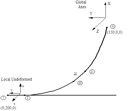
Local Undeformed Axes on a Cable
Flexcom must use instead an algorithm or strategy that does not involve knowledge of the element nodal coordinates. The actual strategy used is this: the local x axis is assumed to be coincident with the global X axis, and the plane formed by the local x and y axes is the plane of the cable itself. Where the cable is defined as initially in the global XY plane, which is frequently the case, the local undeformed axes are coincident with the global axes.
This is the case in the example catenary above. The Flexcom default local undeformed axes are illustrated for Element 1. They are identical for all other elements. Two observations from Default Local Undeformed Axes are appropriate here also. Firstly, if you want to know the orientation calculated by Flexcom for the local undeformed axes of an element defined on a cable, the information you need is in the output file jobname.out. But secondly, and perhaps more importantly, this information is of no particular significance. Looking again at the catenary above, it is clear that it is of little consequence how the undeformed axes of the individual elements are aligned. The important point, as before, is that the undeformed orientation of all elements is the same (the catenary is undeformed when stretched out in a straight line). Flexcom ensures this is the case by default, and will automatically calculate the restoring forces caused by subsequent deformations from this configuration.