Rotational Boundary Conditions and Cables |
 
|
Rotational Boundary Conditions and Cables |
|
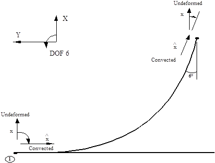
The section concludes with a discussion of one last area where it is necessary to take account of the undeformed orientation of cable elements. This is in the specification of rotational boundary conditions, that is, boundary conditions in any or all of degrees of freedom (DOFs) 4, 5 or 6. Once again the principles involved are best illustrated by means of an example. This is based again on the free hanging catenary of Local Undeformed Axes on a Cable figure; for simplicity it is assumed that a static analysis of the riser in the 2D XY plane is being performed. Suppose it is required to apply boundary condition which will a) prevent rotations about the Z axis (rotations in DOF 6) at Node 1, and b) restrain the riser angle to the vertical to be 6° at Node 51. What values should be specified as the associated Displacement terms for these boundary conditions to apply the desired restraints? It is assumed by that the orientation of the local undeformed axes for the elements of this model is calculated by Flexcom using the program’s default algorithm.
Specifying constant rotational boundary conditions at a node is effectively the same as specifying the orientation of the convected axes for the appropriate element. Because the example is 2D only, the situation here is quite straightforward in that the discussion need be concerned only with specifying the orientation of the appropriate ![]() axes. Consider for example the boundary condition to be applied at Node 1. The restraint proposed is effectively the same as saying the
axes. Consider for example the boundary condition to be applied at Node 1. The restraint proposed is effectively the same as saying the ![]() axis for Element 1 is to be directed along the seabed as shown below. The following diagram shows the orientation of the x (local undeformed) axis for Element 1, as calculated by Flexcom. From the diagram below it is clear that the rotation required to change the undeformed to the convected orientation is -90° (note the sign - a positive rotation in DOF 6 is in the direction from global X to global Y). So at Node 1 the DOF 6 boundary condition is -90°.
axis for Element 1 is to be directed along the seabed as shown below. The following diagram shows the orientation of the x (local undeformed) axis for Element 1, as calculated by Flexcom. From the diagram below it is clear that the rotation required to change the undeformed to the convected orientation is -90° (note the sign - a positive rotation in DOF 6 is in the direction from global X to global Y). So at Node 1 the DOF 6 boundary condition is -90°.
Specification of Rotational Boundary Conditions
A similar reasoning can be used to work out the boundary condition required at Node 51. The orientation of the ![]() axis for the required restraint is shown above. The rotation required to align local undeformed with convected axes is -6° (again note the sign), so this is the value to be specified as the associated Displacement term for the boundary condition.
axis for the required restraint is shown above. The rotation required to align local undeformed with convected axes is -6° (again note the sign), so this is the value to be specified as the associated Displacement term for the boundary condition.