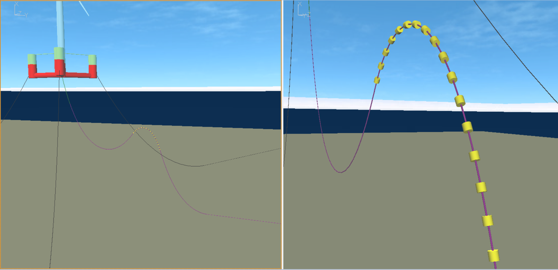
The UMaine reference model does not contain a subsea power cable so a model variation which includes an electrical cable in a lazy wave configuration has been included in the Flexcom example. Two separate models are provided:
•Full model which includes platform, tower, turbine, mooring lines and subsea power cable. You can use this model if you are interested in examining the cable response to the design load cases supplied with the UMaine report. Simply edit the design load case template file (L4-DLCs.keyxm) to restart from the model including the cable (L4-Model_Full_SPC_QS.keyxm), rather than the original model (L4-Model_Full_QS.keyxm).
•Decoupled model which includes the subsea power cable only. This model is intended to be used with displacement RAOs should you wish to pursue this approach instead. This would allow you to quickly assess the relative performance of different cable layouts (e.g. simple catenary, lazy wave, tethered lazy wave etc.).
Here we will focus on the decoupled model of the subsea power cable, illustrating the possibility of estimating cable fatigue damage using Flexcom and Layercom, a related product which examines the cable at a localised cross-sectional level including its armour wires and cable strands.

Full model including platform, tower, turbine, mooring lines & subsea power cable
In the real world, cable fatigue monitoring is facilitated using a range of sensor data, including motion sensors on the floating platform, ADCP current profiling, wave buoy measurements, and distributed temperature sensing included within the cable's fibre optic unit (which can identify electrically induced overheating in the cable). This part of the example illustrates a methodology for estimating fatigue damage accumulation in the cable over time.
Layercom is a local cross-sectional analysis tool which can predict fatigue damage at a local level in various layers of the cross-section. Originally designed for modelling non-bonded flexible risers, it performs stress analysis and fatigue assessment of tensile and pressure armour wires. Given the mechanical similarities between flexible pipes and electrical cables, nowadays Layercom is also used to perform fatigue analysis of subsea power cables. Unlike Flexcom, Layercom is not yet a commercial software product in its own right. It is used internally within Wood and is not offered for sale/rent to external customers. While it is reasonably strong in terms of analytical performance, it currently has some areas which will require further development (e.g. user interface, documentation, examples and validation) before it can be made publicly available.
Displacement RAOs for the floating platform are computed using a series of regular wave simulations at various periods. This example contains separate sections to compute RAOs for both a free-floating platform and a moored platform. Refer to Wave Induced Motion RAOs for further details. The assessment focuses one heading only (head seas), so only the RAOs relating to surge, heave, and pitch are relevant.
If you are using a decoupled model of the subsea cable, the displacement RAOs should be representative of a moored platform and ideally include the effects of wind loading on the rotor. However the wind thrust is difficult to account for accurately using this modelling approach, given that the platform RAOs at each wave frequency are generated from regular waves of small amplitude (consistent with the assumption that RAOs scale linearly with increasing wave heights), whereas wind thrust is inherently linked to wave height (as evidenced by joint probability distributions of wind speed and wave height). One possible approach to use when computing moored platform RAOs is to apply a steady wind in each regular wave simulation which corresponds to the most probable wind speed at that particular wave frequency. Wave frequency readily converts to wave period, and the most probable wave height associated with each wave period may be obtained from a wave scatter diagram. Then an appropriate wind speed, the one with the highest probability, may be retrieved from a wind-wave joint probability distribution. The UMaine report (Allen et al., 2020) does not provide full details of the environmental conditions at the Maine site, so wind effects are omitted from the computation of moored platform RAOs for simplicity.
An alternative approach is to use a fully coupled model, which removes any uncertainty regarding the use of displacement RAOs. This is more accurate but more computationally intensive, and could be reserved as a final verification of a cable design based on a decoupled model.
Real-world environmental data is available from a range of sources. As an illustration, metocean data has been downloaded from Ireland’s Digital Ocean for the AMETS Berth A wave buoy (located off the west coast of Ireland) and shipped with this example. This database contains historic data dating back to 2012. For illustrative purposes, one year of data (2022) was downloaded and incorporated into this example. When computing fatigue damage accumulation over time, environmental conditions are typically sub-divided into blocks of time, with the overall conditions assumed to remain relatively stable over each block. Each time slot may be modelled using a single Flexcom simulation, with the maximum wave height occurrence, and its associated period and direction, being simulated as a regular wave (this approach is computationally efficient and inherently conservative). 3-hour or 6-hour time slots would provide reasonable detail, and this will lead to a large number of Flexcom simulations in order to replicate one year in the life of the subsea cable. For the purposes of this example, the environmental data is simply divided into 12 slots, each of 1 month duration. Standard Excel formulae were used here but ideally a VBA script would be written to provide more power and flexibility. Naturally the monthly breakdown is very conservative as the maximum wave will not be experienced at all times during each month. Current data for the site is unavailable, hence random current speeds have been fabricated, and the current direction assumed to be aligned with the wave direction.
Wind loading on the platform will cause it to drift into an offset position. No platform offset data is available in this case (this would come from motion sensors). The magnitude and direction of platform offset may be estimated by applying a steady wind corresponding to the wave loading which is being applied. As noted above however, the wind-wave joint probability distribution is unavailable, so for simplicity the platform offset is assumed to be some percentage of wave height (which in turn is typically related to wind speed).
Each time slot from the wave buoy data is modelled using a series of Flexcom simulations - initial static, offset, current and regular wave.
Fatigue analysis in Flexcom requires tension and curvature information at all points of interest along the cable. The location of critical fatigue damage will not be known in advance because the touchdown zone is continually moving due to the ever-changing platform position and environmental loading direction etc. Hence it makes sense to store tension and curvature time histories for all nodes in the model. To simplify the input files, data is stored at every 10th node in this example.
Each regular wave simulation is analysed for 10 wave periods in Flexcom to allow the system to reach steady-state response, with data from the last two periods being stored for subsequent use by Layercom during local analysis. The fatigue damage computed by Layercom must be subsequently scaled up from 2 wave periods to the length of the time slot which the simulation represents (1 month in this case) to produce a fatigue damage corresponding to the time period under consideration.
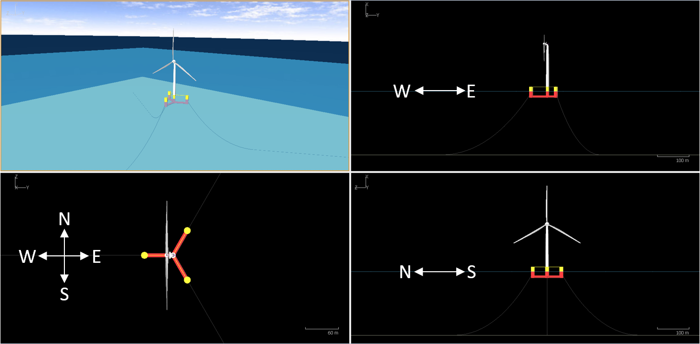
The Flexcom model of the subsea cable must be constructed in its real-world orientation with respect to the cardinal directions (North, South, East, West). This is essential to ensure consistency between the structural orientation of the subsea cable and the directionality of the environmental loading. The figure below illustrates the FOWT model, with compass directions included, in isometric (upper left), plan (lower left), side elevation (upper right) and front elevation (lower right). The leading mooring line faces West, towards the prevailing weather conditions. The subsea cable is located between the leeward mooring lines, facing East. You can see from the figure that positive X is vertical/upward, positive Y is aligned with East and positive Z is aligned with North.

Relationship between compass directions and Flexcom axes
Some care is needed also with regard to the applied loads. Wave direction from the wave buoy data means coming from, and is measured clockwise from North at 0degrees (i.e. N=0°, E=90°, S=180°, W=270°). Wave direction in Flexcom means going towards, and is measured anticlockwise from positive Global-Y axis at 0degrees (i.e. N=270°, E=180°, S=90°, W=0°). Hence to convert from compass directions to Flexcom conventions, the following adjustments are made.
•Multiply by -1 to convert from 'coming from' to 'going towards'
•Add 270° to align North at 0° to North at 270°
The Layercom model contains local cross-sectional information relating to the subsea cable. It also contains fatigue related data such as S-N curves which relate the number of stress cycles to fatigue damage. The time histories of effective tension and curvature coming from Flexcom are two wave periods in duration. Hence the fatigue damage computed by Layercom is scaled up from 2 wave periods to the length of the time slot which the simulation represents (1 month in this case) to produce a fatigue damage corresponding to the time period under consideration. Finally, the fatigue damage is summed across all time slots to produce an estimate of total fatigue damage which has accumulated in the cable during the study period (1 year in this case).