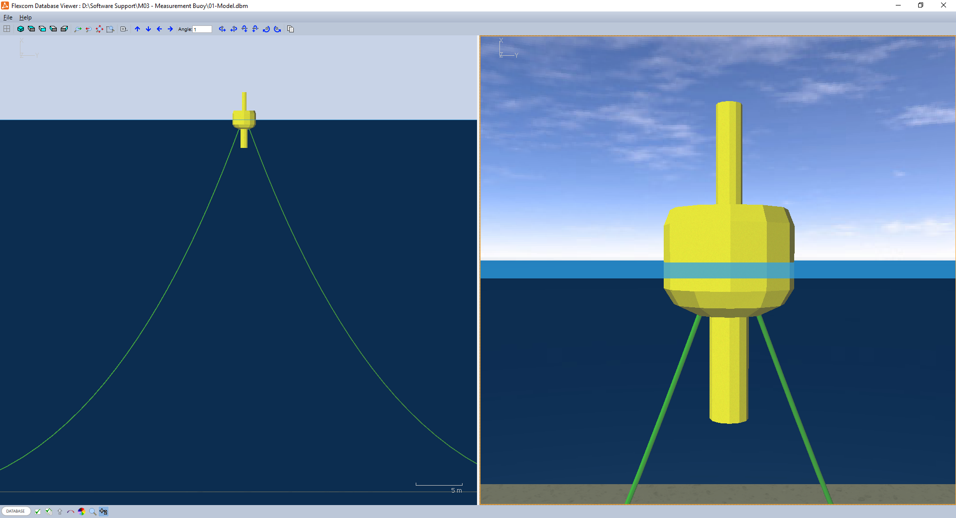
Wave measurement buoys are deployed to measure the water surface elevation as a function of time. This data can be logged for subsequent processing, providing statistical information such as significant wave height (Hs), mean up-crossing period (Tz), and wave directionality. The buoy considered in this example has a steel core with buoyancy material attached to it. The float is 2.5m in diameter and 2.0m high. It is situated in 40m water depth and is held on station using two mooring ropes.
This example is based on a wave measurement buoy which was deployed at the SmartBay test site, Ireland's national observation and validation facility for the ocean energy sector.

Wave Measurement Buoy
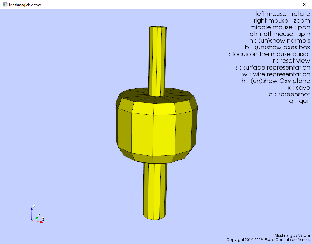
A hydrodynamic analysis of the buoy is performed in NEMOH, in order to compute its hydrodynamic characteristics. This data is then passed into Flexcom where it is combined with the structural model to examine the global response of the system. The image below shows the mesh discretisation used in the hydrodynamic simulation (the mesh visualisation is provided by Meshmagick).

Hydrodynamic Mesh illustrated by Meshmagick
The buoy profile is created approximately using a spreadsheet (see 'M03 - Measurement Buoy.xlsx'). It is sub-divided into a series of horizontal sections along its length, corresponding to the changes in diameter. Each section is modelled using 12 points which are equally spaced around the circumference at 30 degree intervals. Hydrodynamic meshes are typically derived from detailed specification drawings (e.g. AutoCAD) but in the case of this relatively simple shape, it was feasible to create it in a spreadsheet. It is not necessary to include any part of the body which lies above the water line, but the full body is modelled, as no further mesh creation is required if the body's draft is altered subsequently (e.g. due to additional weight imparted by mooring lines). The hydrodynamic analysis is performed by running NEMOH, and the hydrodynamic characteristics are converted into Flexcom format using the Hydrodynamic Data Importer.
The buoy is modelled using a straight Line along its central axis. Line Locations are used to position finite element nodes at the centres of gravity and buoyancy. The line is assigned rigid Stiffness terms as it is assumed to act as a rigid body. The line is assigned a Mass per Unit Length of zero (as the total mass is concentrated at the centre of mass), a Buoyancy Diameter of zero (as buoyancy effects are modelled at the centre of buoyancy). Hydrodynamic drag is set to zero in order to suppress the application of viscous drag loads via Morison's equation (although realistic Drag Diameters are specified should you wish to add viscous drag yourself subsequently).
An individual Floating Body is defined to model the buoy's hydrodynamic response. Inertia terms are specified at its centre of gravity. Hydrostatic Stiffness terms are used to simulate restoring forces and moments due to buoyancy. Added Mass, Radiation Damping and Force RAO coefficients are obtained from the NEMOH simulation - these terms enable the computation of incident, diffracted and radiated wave loading.
An auxiliary profile is used to represent the physical profile of the buoy. While this has no structural function, it enhances the visual appeal of the model, and assists in the understanding of motions post-simulation. The profile is created from the 'Description_Full.tec' file which is created by NEMOH's meshing algorithm.
One short line is used to create a connecting frame to link the buoy with its mooring lines. The frame is assigned large Stiffness terms to simulate rigidity, and a Mass per Unit Length of zero for simplicity. It is not intended to induce any hydrodynamic loading, so it is assigned zero values of Buoyancy Diameter and Drag Diameter. The Equivalent Nodes feature is used to attach the frame to the buoy.
The mooring lines are created using 2 separate Lines. The upper end of each mooring line is attached to the connecting frame using a Hinge Element, while the lower ends are constrained using Fixed Boundary Conditions. Realistic Stiffness, Mass per Unit Length, Buoyancy Diameter and Drag Diameter terms are assigned to the mooring lines.