L06 - IEA 22MW RWT |
 
|
L06 - IEA 22MW RWT |
|
This example considers the IEA 22 MW reference wind turbine and recreates the model in Flexcom. Full details of the turbine are provided in the official definition document (Zahle et al., 2024) while some of the main aspects are briefly summarised here.
Three separate Flexcom models are actually provided in this example:
•Tower model. This model contains the 22 MW wind turbine supported by a tower only. The tower model is analysed in both operational and parked states. The operational case formed the basis of the original example in Flexcom, and these results include a code-to-code comparison of simulation models built using OpenFAST, OrcaFlex and Flexcom. Full details of these numerical models and the benchmarking exercise may be found in Britton et. al., 2025. Consistent with the copyright agreement, the authors hereby acknowledge ASME as the original publisher and copyright holder. The parked cases, braked and idling, were added later, and these models compare results from OpenFAST and Flexcom.
•Monopile model. This model contains the wind turbine hosted on a fixed monopile. The monopile model is analysed in simplified operational conditions broadly corresponding to DLC1.0 (no wind shear, turbulence, or yaw misalignment). For illustrative purposes, a time varying wind load is applied in a single continuous simulation. The time history of wind speed starts off at 4 m/s, and gradually increases over time in steps of 1 m/s up to 25 m/s.
•Semi-Submersible model. This model contains the wind turbine hosted on a floating semisub. The semisub model is also analysed using stepped wind, as per the monopile model.
The turbine was jointly developed by DTU and NREL. The main components of the turbine were designed sequentially with multidisciplinary design tools. The rotor was designed using DTU’s in-house Aero-Structural Optimization Framework for Wind Turbines (AESOpt) and aeroelastic code HAWC2. NREL’s Wind-Plant Integrated System Design and Engineering Model (WISDEM) and Wind Energy with Integrated Servo-control (WEIS) toolchains were used to design the drivetrain, tower, monopile, and semisubmersible floater. The turbine was designed primarily with medium-fidelity aeroelastic modelling (such as in Flexcom).
The IEA 22 MW RWT data is open source and is available on the IEA Wind Systems GitHub site IEA Wind Systems GitHub. The primary file format used to define dimensions and properties of the turbine is the WindIO format. Aero-servo-hydro-elastic input files to model the turbine in various modelling tools (including Flexcom) are also available in the repository.
The main properties of the IEA 22 MW reference wind turbine are as follows:
Parameter |
Value |
Parameter |
Value |
|---|---|---|---|
Rated power |
22 MW |
Blade length |
137.8 m |
Specific power |
351.41 W/m2 |
Blade prebend |
7.0 m |
Wind class |
1B |
Blade mass |
82.301 t |
Rotor orientation |
Upwind |
Airfoil series |
FFA-W3 |
Number of blades |
3 |
Blade root diameter |
5.8 m |
Control |
Variable speed, collective pitch |
Rotor precone angle |
4.0 deg |
Cut-in wind speed |
3.0 m/s |
Shaft tilt angle |
6.0 deg |
Rated wind speed |
11.0 m/s |
Hub height |
170.0 m |
Cut-out wind speed |
25.0 m/s |
Drivetrain |
Direct |
Design tip-speed ratio |
9.153 |
Generator efficiency at rated load |
95.4% |
Min. rotor speed |
1.807 rpm |
Hub system mass |
120.0 t |
Max. rotor speed |
7.061 rpm |
Nacelle assembly mass (ex. hub) |
821.2 t |
Max. blade tip speed |
105.0 m/s |
Tower mass |
1,574 t |
Rotor diameter |
284.0 m |
Monopile mass |
2,097 t |
Hub diameter |
8.4 m |
The 22 MW RWT has a hub height of 170 m, with a 5.614 m vertical distance between the rotor apex and tower top. The tower is assumed to start 15 m above mean sea level and its length is therefore 149.386 m. The monopile is designed for a water depth of 34 m and its length in the seabed is 45 m, giving a total length of 94 m to reach the tower base. The assembly also includes a transition piece, which is modeled as a simple point mass of 100 t and is located between tower and monopile 15 m above mean sea level. The hub height of 170 m leaves a clearance of 30 m between mean sea level and blade tip (not including loaded deflections). This clearance is computed as hub height minus the rotor radius times the cosine of hub precone and shaft tilt angles.
The floating platform design maintains the same semisubmersible architecture used in the VolturnUS-S platform, with three outer columns and a center main column. Since structural analysis was not performed in the initial design, the size of the lower pontoons was simply increased to 10 m. The same tower as the fixed-bottom turbine is used.
Parameter |
Value |
|---|---|
Platform type |
Semisubmersible |
Freeboard |
15 m |
Draft |
25 m |
Total system mass |
23,984.1 t |
Platform mass |
21,165.6 |
Water depth |
200 m |
Mooring system |
Three-line chain catenary |
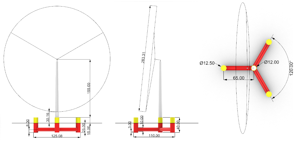
Designed dimensions of the IEA 22 MW RWT semisubmersible platform