The nodal deformation vector of an element is as follows, dnd,

where u, v, w are translational deformations in the convected axis system, Ru, Rv, Rw are rotational deformations about the convected axes, and the subscripts 1 and 2 refer to the start and end nodes of the element, respectively. The final two terms in the vector, N and T, and the axial force and torque terms for the element, respectively. Unlike the other terms, these are not deformations (i.e. εA and εT), as Flexcom's hybrid beam-column element solves for the axial force and torque terms directly, independent from the nodal displacement terms. This is also the reason why the nodal deformation vector contains 14 entries, two more than that of a standard 3D beam element.
The local deformation vector at any point along the element, udef(x), is related to the nodal deformation vector of the element, dnd, by the matrix of shape functions, [N(x)].
![]()
The beam element uses different shape functions for the various deformation modes, hence the shape function matrix for a beam uses a combination of linear and Hermitian shape functions:

Defining ζ = x / L gives the linear interpolation functions as:
![]()
![]()
The Hermitian interpolation functions are:
![]()
![]()
![]()
![]()
So the local axial displacement u along the element is interpolated using a linear shape function, while the transverse components v and w are interpolated using Hermitian shape functions which are cubic/third order with respect to ζ. It is not required to interpolate the penalty terms N and T as these are assumed constant along the element, hence the corresponding entries in the shape function matrix are zero.
The linear stiffness matrix [KL] is defined as:
![]()
Here [D] is the constitutive matrix which relates the stress and strain vectors:

EA is the axial stiffness, GJ is the torsional stiffness, and EIyy and EIzz are the bending stiffnesses about the local convected Y and Z axes respectively.
[B(x)] is the matrix of functions relating the linear strain to the nodal deformation vector.
The linear stiffness matrix [KL], including the axial penalty terms, may be derived as:

For beam-column elements, γ1 is related to the ratio of the bending to axial stiffness (γ1 = EI / EA.L2), while γ2 is the ratio of the bending to torsional stiffness (γ2 = EI / GJ). The parameters ρ1 and ρ2 are flexibility coefficients with default values of 0.001 and 0.1, respectively.
The geometric stiffness matrix [KG] is defined as:
![]()
Here [Aσ] is a 2x2 matrix based on effective tension T:
![]()
and [G(x)] is the matrix that relates a vector of slopes to the nodal deformation vector. [G(x)] is found by differentiating the second and third rows of the shape function matrix [N(x)] with respect to x and is given by:

The geometric stiffness matrix [KG] may be derived as:

Note that the above exact form of the geometric stiffness matrix assumes that the effective tension T is constant along the element. This is not the case in general, so the geometric stiffness matrix is found using numerical integration.
The initial displacement matrix [KD] is defined as:
![]()
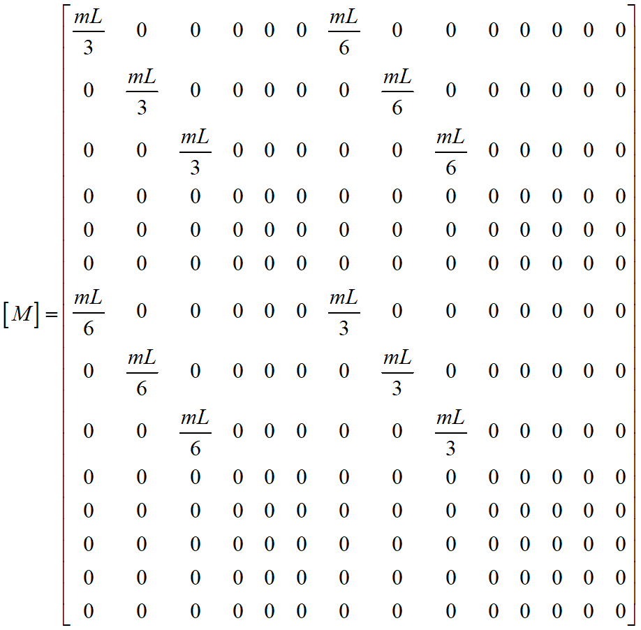
The mass matrix [M] is defined as:
![]() (11)
(11)
where the density matrix [m] is defined as:
 (12)
(12)
and m is the mass per unit length of the element (which includes contributions from internal fluid and hydrodynamic added mass, if appropriate).
Hence the mass matrix [M] may be derived as:

The Damping matrix [C] for a beam element is formed as a linear combination of the stiffness and mass matrices:
![]()
In the case of Deformation Mode Damping, the damping matrix is based on different components in the axial, bending and torsional degrees of freedom:
![]()