Yaw Alignment Demo |
 
|
Yaw Alignment Demo |
|
All of the UMaine design load case conditions consider a wind heading of zero degrees. This test case is designed to illustrate how wind may be applied from various directions using InflowWind, and how to align the turbine to face the oncoming wind using ServoDyn. The example simulates a steady wind speed of 10m/s from various directions at intervals of 45 degrees around the compass.
•Wind direction is controlled by the PropagationDir parameter in the InflowWind input file. In the AeroDyn coordinate system, wind angle is measured positive clockwise from the X axis in plan view (positive rotates towards negative Y axis). Hence in the Flexcom coordinate system, wind angle is measured positive clockwise from the global Y axis in plan view. This means that the directionality convention for wind loading in Flexcom is not consistent with the directionality convention for wave and current loading (which is measured positive anti-clockwise from the global Y axis). This is quirk of the Flexcom-OpenFAST coupling and something which you need to be aware of. For example, if you have specified a wave direction of +90 degrees, and you wish to align wind and wave loading, then you would set PropagationDir to -90 degrees.
•Regarding turbine orientation, a fundamental aspect of all Flexcom models is that the turbine is initially aligned with the negative sense of the global Y axis in plan view. This is a necessary requirement in order to align the coordinate systems of Flexcom and AeroDyn. Hence a turbine yaw angle of zero degrees corresponds to this orientation. Given that the wind direction is constant in each case in this example, active yaw control is not considered. Instead the mean turbine yaw for each case is set using the YawNeut parameter in the ServoDyn input file. In the Flexcom coordinate system, turbine yaw angle is measured positive anti-clockwise from the negative global Y axis in plan view. For example, if you have specified a wind direction of -90 degrees via PropagationDir, and you wish to align the turbine to face the oncoming wind, then you would set YawNeut to +90 degrees.
For modelling simplicity, this section considers the turbine and supporting tower only, without the floating platform and mooring system.
The following plan views show the turbine yaw orientation corresponding to the various wind directions.
 PropagationDir 0deg, YawNeut 0deg |
 PropagationDir -45deg, YawNeut 45deg |
 PropagationDir -90deg, YawNeut 90deg |
 PropagationDir -135deg, YawNeut 135deg |
 PropagationDir -180deg, YawNeut 180deg |
 PropagationDir -225deg, YawNeut -135deg |
 PropagationDir -270deg, YawNeut -90deg |
 PropagationDir -315deg, YawNeut -45deg |
Turbine Response
The following plots illustrate the turbine response for the various wind directions.
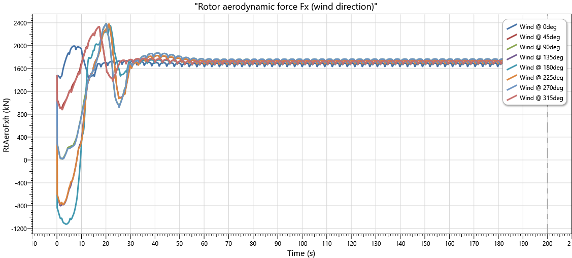
•Rotor aerodynamic force. The aerodynamic force in the wind direction should be independent of wind direction and turbine yaw orientation, as the rotor plane is always perpendicular to the wind direction. Results from the Flexcom simulations show close agreement between the various wind directions. Some minor fluctuations are evident but the mean force is consistent for the various wind directions.
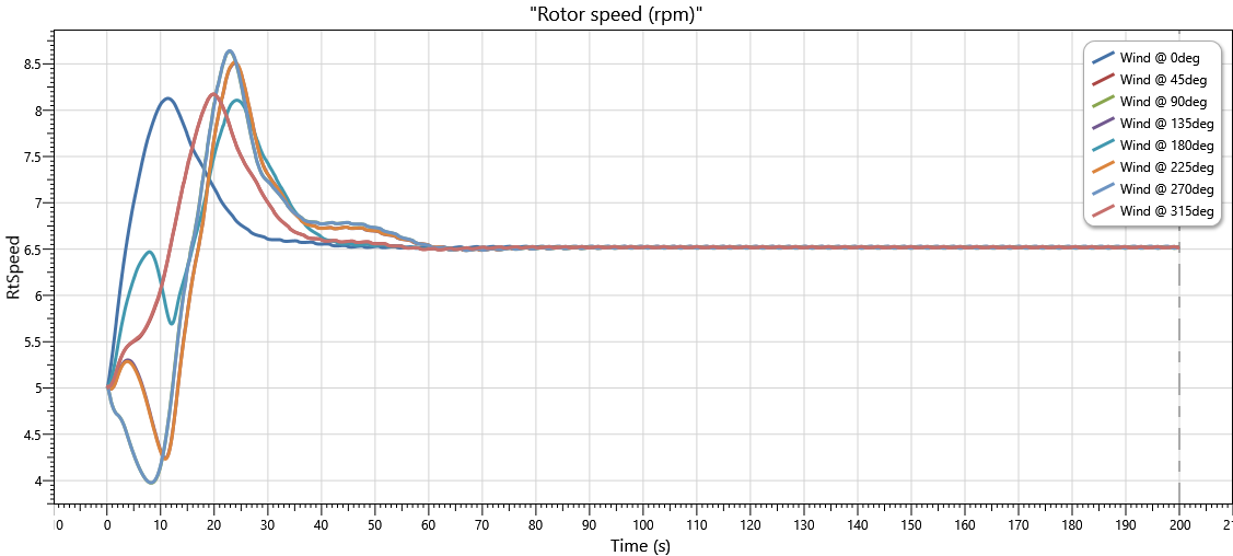
•Rotor speed. Apart from some initial transience where the turbine is yawing to the correct orientation, the rotor speed is independent of wind direction.
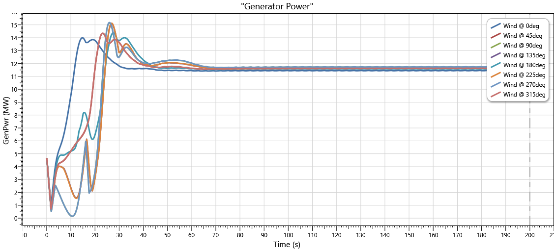
•Generator power. Generator power should also be independent of wind direction. Like aerodynamic force, the generator power estimated by Flexcom shows close (but not exact) agreement across the various wind directions. .
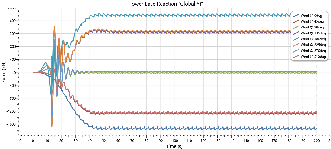
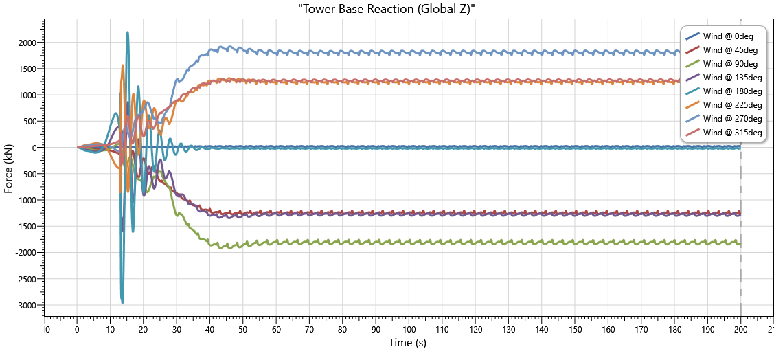
•Tower base reaction forces. Unlike the rotor aerodynamic force which is presented in the local rotor axis system, the reaction forces at the base of the tower are presented in Flexcom's global axis system. These plots demonstrate the correct application of wind loads from AeroDyn to the Flexcom model. Reactions in global Y begin with the (negative) magnitude of the aerodynamic force for a 0degree wind, then gradually reduce to zero from 0degrees to 90degrees, before increasing to a maximum value at 180degrees, and so on. The reverse is true for the global Z reactions.