Huses Model |
 
|
Huses Model |
|
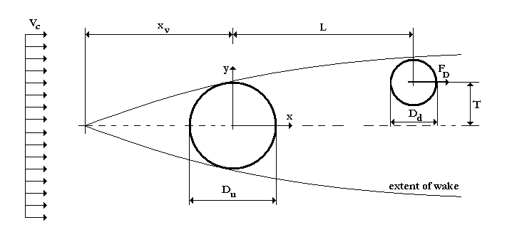
The basic arrangement of Huse (1993) wake flow model is illustrated in the figure below.
Huse’s Model
The current impacts on the upstream structure with velocity Vc, giving rise to the wake region. L and T denote the centre to centre longitudinal and transverse separations between the upstream and downstream structures. Huse’s model introduces three coefficients to determine the profile of the reduced current velocity. The default values for these coefficients are k1=0.25, k2=1 and k3=0.693, respectively. The drag load on the downstream structure is evaluated using the reduced current velocity instead of the undisturbed current velocity Vc. In the equations that follow the u subscript refers to the upstream structure and the d subscript to the downstream structure, respectively.
The decrease in the in-line water particle velocity in the wake region (the wake velocity) is represented by u.
 (1)
(1)
To examine this velocity in more detail, it is convenient to define several parameters. The peak wake velocity, U0, is the wake velocity along the centre line of the wake (y=0).
 (2)
(2)
The wake half-width, b, is the distance from the centre line of the wake to the point at which the wake velocity is equal to half the peak wake velocity.
![]() (3)
(3)
The three Equations above (1) to (3) are strictly valid only some distance downstream of the cylinder. Very close to the structure they give a wake peak which is too high and narrow (Huse, 1993), which will lead to erroneous results in calculating the wake peak. To correct for this, Huse introduces the concept of a “virtual” wake source. In Equations (2) and (3) the term x is now replaced by xs.
![]() (4)
(4)
At the centre of the upstream cylinder, the half-width of the wake is equal to half of the diameter of the structure. In order to calculate the location of the wake source, Equation (3) is used, with x taken at the centre of the upstream structure. At this location, x is 0 and Equation (4) becomes:
![]() (5)
(5)
Therefore, substituting Du/2 for b and xs for x in Equation (3) allows the location of the wake source to be determined as:
![]() (6)
(6)
The reduced current velocity is determined as:
![]() (7)
(7)
As a result, the drag force on the downstream structure is:
![]() (8)
(8)
•*WAKE UPSTREAM is used to specify the composition of the upstream structure in terms of element sets, for use in wake interference calculations. The keyword also selects the wake interference model to be used, and defines associated data to characterise the wake field. Specifically, the TYPE=HUSE inputs are used to specify parameters relating to Huse’s wake interference formulation.