Blevins Model |
 
|
Blevins Model |
|
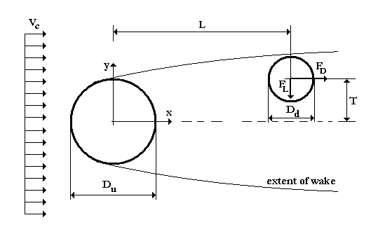
The basic arrangement of Blevins (2005) wake flow model is illustrated in the figure below.
Blevins’ Model
The current impacts on the upstream structure with velocity Vc, giving rise to the wake region. L and T denote the centre to centre longitudinal and transverse separations between the upstream and downstream structures. Blevins' model introduces three coefficients to determine the profile of the reduced current velocity and the coefficient of lift. The default values for these coefficients are a1=1, a2=4.5 and a3=-10.6, respectively. The drag load on the downstream structure is evaluated using the reduced current velocity instead of the undisturbed current velocity Vc. The lift force acts towards the centre line of the wake and is evaluated based on the lift coefficient determined from this wake model. In the equations that follow the u subscript refers to the upstream structure and the d subscript to the downstream structure, respectively.
The decrease in the in-line water particle velocity in the wake region (the wake velocity) is represented by u.
![]() (1)
(1)
where N is the decaying factor:
 (2)
(2)
and b is:
![]() (3)
(3)
The reduced current velocity is:
![]() (4)
(4)
As a result, the drag force on the downstream structure is:
![]() (5)
(5)
The lift coefficient is:
![]() (6)
(6)
The lift force on the downstream structure is:
![]() (7)
(7)
•*WAKE UPSTREAM is used to specify the composition of the upstream structure in terms of element sets, for use in wake interference calculations. The keyword also selects the wake interference model to be used, and defines associated data to characterise the wake field. Specifically, the TYPE=BLEVINS inputs are used to specify parameters relating to Blevins wake interference formulation.