Von Mises Stress (Standard Method) |
 
|
Von Mises Stress (Standard Method) |
|
The standard or default formulation used by Flexcom in calculating von Mises stress is derived with reference to the figure below, which shows two equivalent representatives of the in-wall stresses induced by tension and internal and external pressures in a general thick walled riser section.
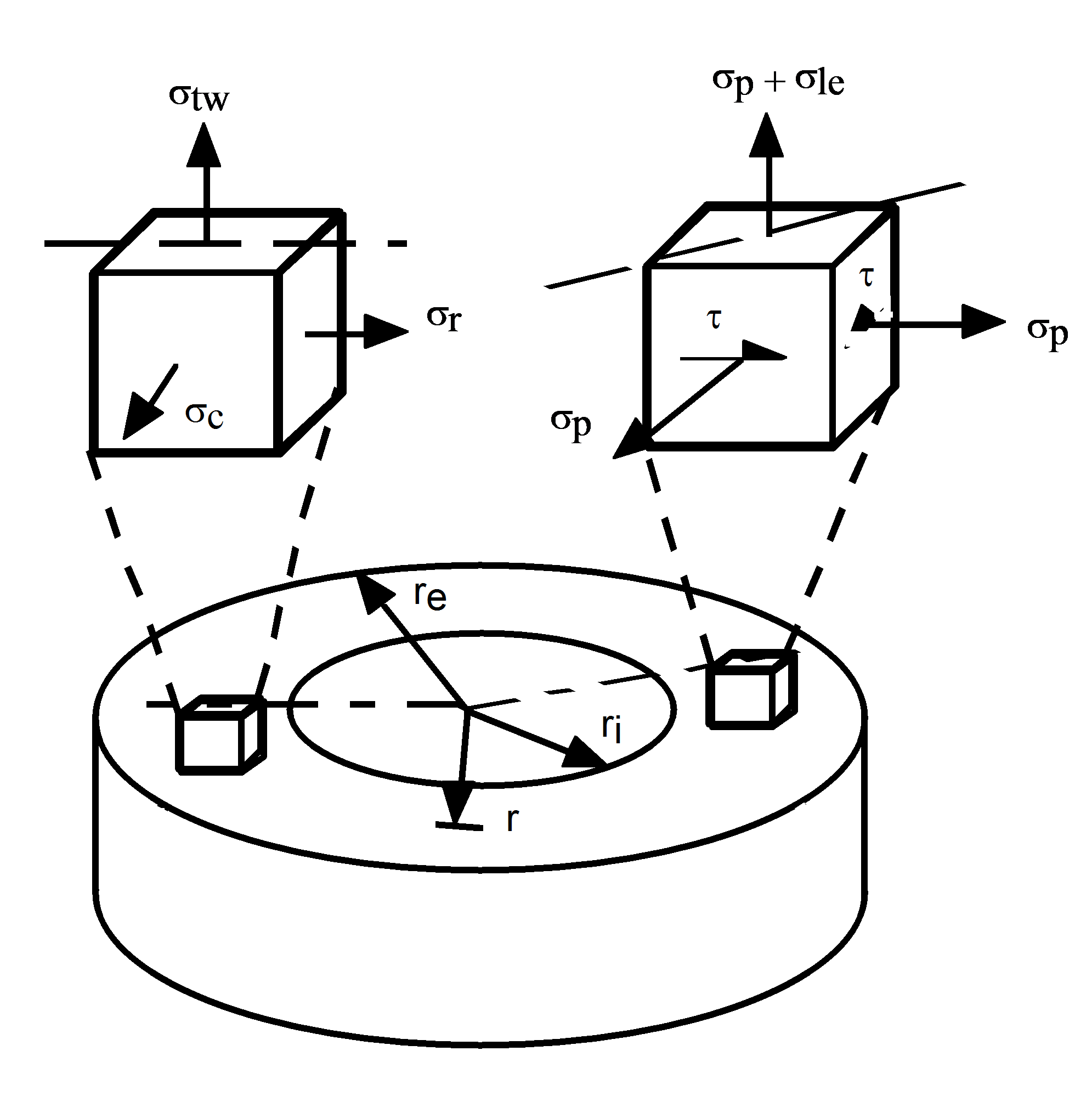
Riser In-Wall Stress System
In the representation on the left, σtw represents the “true wall” axial stress as defined in Axial Stress (Eq.1). σc is the circumferential or hoop stress, and σr is the radial stress. σtw is as noted constant over the section, but σc and σr are functions of r, the radius. However, the mean of the two stresses is everywhere constant, and alternative expressions for σc and σr may be written using Lamé’s equations as follows:
where:
and:
![]() (3)
(3)
Here, pi and po again represent internal and external pressure, and Di and Do are effective internal and outer diameters. σp is a constant hydrostatic stress and τ is a distortional shear stress, as shown in the representation on the right in the above Riser In-Wall Stress System figure. The effective stress σle is defined by:
![]() (4)
(4)
where Teff is the effective tension. Equation (4) above can be rewritten as:
![]() (5)
(5)
as shown in the above Riser In-Wall Stress System figure. The effective stress is the amount by which the axial wall stress σtw exceeds the in-wall hydrostatic stress σp, and is analogous to the deviatoric term used in solid and soil mechanics.
The von Mises stress, σvm, for the triaxial system of the above Riser In-Wall Stress System figure is given by:
![]() (6)
(6)
Substituting from the Equations above gives an equivalent formulation:
![]() (7)
(7)
The von Mises stress is therefore closely related to the effective stress, rather than the “true wall” stress, as would be expected from the above Equation, since it is obvious that the hydrostatic stress σp can have no effect on the von Mises stress.
Of course, when the pipe of the above Riser In-Wall Stress System figure is subjected to bending in addition to tensile and pressure forces, the resultant bending stress (σb say) must be added to σle when calculating σvm. Therefore the Equation directly above becomes:
![]() (8)
(8)
In this case, the von Mises stress must be checked on the pipe inner surface, where τ is a maximum, and on the outer surface, where ![]() is a maximum. For this reason Flexcom calculates σvm on both the inside and the outside surface to find the maximum value.
is a maximum. For this reason Flexcom calculates σvm on both the inside and the outside surface to find the maximum value.
By default, Flexcom outputs the maximum von Mises stress occurring on the cross section. However, when you request a plot of von Mises stress, you can optionally specify a location around the element circumference where von Mises stress is to be computed. The location is specified in terms of an integer value (N) which corresponds to an angle θ, measured in degrees anti-clockwise from the local element cross-section y-axis. The table below indicates the variation of parameter N with θ for von Mises stress calculations. In this table, σVMI represents von Mises stress on the element inner surface, while σVMO represents von Mises stress on the element outer surface.
Location Parameter for von Mises Stress Calculations
θ° |
N |
|
σVMI |
σVMO |
|
0 |
1 |
9 |
45 |
2 |
10 |
90 |
3 |
11 |
135 |
4 |
12 |
180 |
5 |
13 |
225 |
6 |
14 |
270 |
7 |
15 |
315 |
8 |
16 |