Buoyancy Formulations |
 
|
Buoyancy Formulations |
|
Flexcom provides two options for specifying how buoyancy forces on an element are determined, as follows:
•Default buoyancy
•Distributed buoyancy
Theory
The Default buoyancy formulation, calculates the total buoyancy force on each element as the sum of two components. These are:
i) the pressure forces normal to the riser cross-section, and
ii) the pressure forces on the ends of the element. These components are illustrated in the figure below.
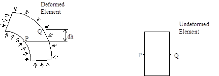
Buoyancy Components on Riser Element
An expression for the first of these terms is readily derived by integrating around the circumference the net differential pressure experienced between opposite points on the circumference (such as P and Q in the figure above), due to riser rotation and deformation. The second term, the element end forces, is calculated simply as ρwgAοh, where ρw is the mass density of seawater, g is the gravitational constant, Aο is the external area (calculated from the effective buoyancy diameter), and h is hydrostatic head.
Buoyancy forces calculated for individual elements are accumulated in the global force vector for the total structure. Where there is no change in external area (Ao) between adjacent elements, the element end forces cancel out when the total force vector is assembled; this is illustrated schematically in Figure (A) below. Where there is a change in cross section, a net force based on the change in areas between the two elements results, as illustrated in Figure (B) below.
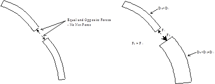
(A) No Change in Cross-Section (B) Change in Cross-Section
Forces on Adjacent Elements
For the majority of analyses, this default buoyancy formulation provides the most realistic and accurate approach to modelling the buoyancy forces on the elements. In a small number of cases, however, this may not provide the most realistic buoyancy model.
Consider the rigid riser shown schematically in the figure below. It consists of a number of riser joints, many with a foam buoyancy section attached. The buoyancy forces generated by the foam sections are transferred to each riser joint by a reaction plate, located close to the top of the joint. A close-up of a single joint is shown for clarity.

Rigid Riser with Discrete Buoyancy Units
The most convenient way to model this structure using Flexcom is to adopt a smeared buoyancy approach, where the section over which the foam buoyancy units are distributed is modelled as a single line of elements with appropriate buoyancy diameter, as shown in the figure below. If this approach is taken with the Default buoyancy option, it will however result in a large upward buoyancy force at the base of the buoyancy section, with no additional buoyancy forces above this point (because there is no change in section). Such a model will correctly predict the effective tension distribution in the riser, and hence the riser bending response. However the distribution of axial extension and axial force will not be correctly predicted.
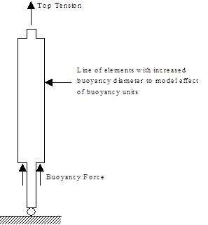
Simplified Riser Model with Distributed Buoyancy
This problem could be readily overcome by modelling the riser and buoyancy units separately (but connected at the reaction plates), but this could be quite tedious to set up (particularly in earlier versions of the software, which did not possess the *LINE SECTION GROUPS keyword which facilitates the creation of repeating sub-sections). An alternative approach is to use the Distributed buoyancy formulation. With this formulation, the buoyancy forces generated by the riser itself (that is, the riser without buoyancy material attached) are calculated as before, but the buoyancy loads generated by the buoyancy material are applied as a distributed vertical load along the riser. This more closely matches the situation in reality, and correctly predicts the effective tension distribution, the axial force distribution and the axial extension of the riser.
If you use the distributed buoyancy option, then you must provide a value for the actual outer diameter of the riser (without buoyancy material). Flexcom uses this value to calculate the buoyancy loads generated by the riser itself. The program then assumes that buoyancy material completely surrounds the riser, extending out as far as the specified effective buoyancy diameter, and calculates the distributed buoyancy loading generated by this material.
It should be stressed that for the majority of analyses, the default buoyancy option provides the most accurate way of modelling the situation in reality. It is only in a small number of cases (such as that described above) where buoyancy loads generated by a large number of discrete buoyancy units may be approximated by a distributed load, that the distributed buoyancy option should be used.
•*GEOMETRIC SETS is used to assign geometric properties to element sets, including the specification of buoyancy diameter, and the selection of buoyancy formulation.
If you would like to see an example of how buoyancy modules are modelled using a smeared/distributed buoyancy approach, refer to A01 - Deepwater Drilling Riser.
If you would like to see an example of how buoyancy modules are modelled explicitly, refer to K01 - Worked Example - Simple.