Model |
 
|
Model |
|
The options under the Model heading are as follows:
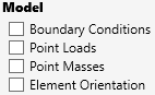
•Boundary Conditions (indicated by a green pyramid centred on the constrained node)
•Point Loads (indicated by a sphere centred on the relevant node, with an arrow showing the load direction)
•Point Masses (indicated by a cube centred on the relevant node)
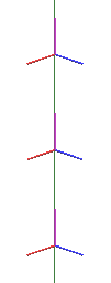
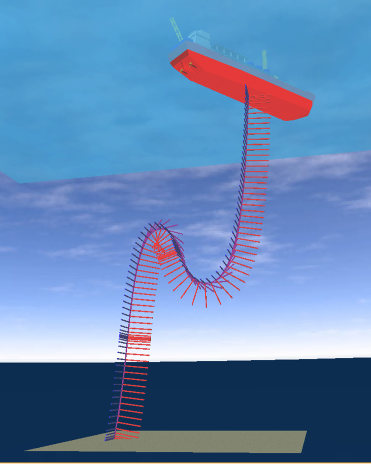
•Element Orientation
oThis feature displays the local convected axes for each element. Flexcom uses a convected coordinate axes technique for modelling finite rotations in three dimensions. Each element of the finite element discretisation has a convected axis system associated with it, which moves with the element as it displaces in space. Refer to Finite Element Formulation for further details.
oKey: Purple is local x-axis, Red is local-y axis, Blue is local-z axis.