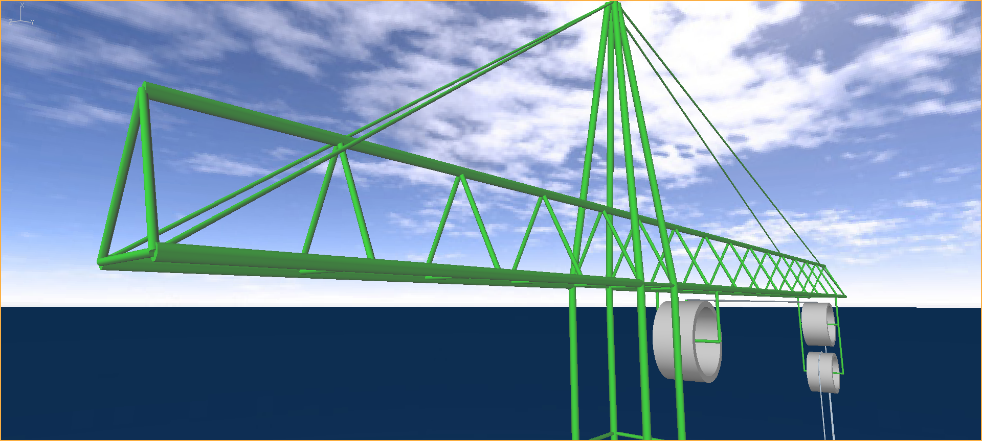
In this particular model, the tower and jib are included for cosmetic purposes only, so they are represented by auxiliary elements. Tubular lattice structures may be modelled by Flexcom (as illustrated in Example L03 - OC4 Jacket) but the supporting framework is omitted here for simplicity.

Tower & Jib Auxiliary Elements
The pulleys are modelled using cylindrical guide surfaces with relatively high contact stiffness to prevent any significant penetration of the pulley surfaces by the cable. The tower pulley in particular, has a very high contact stiffness which is capable of withstanding the compressive radial loads exerted by multiple wraps of cable as the block is lifted upwards.
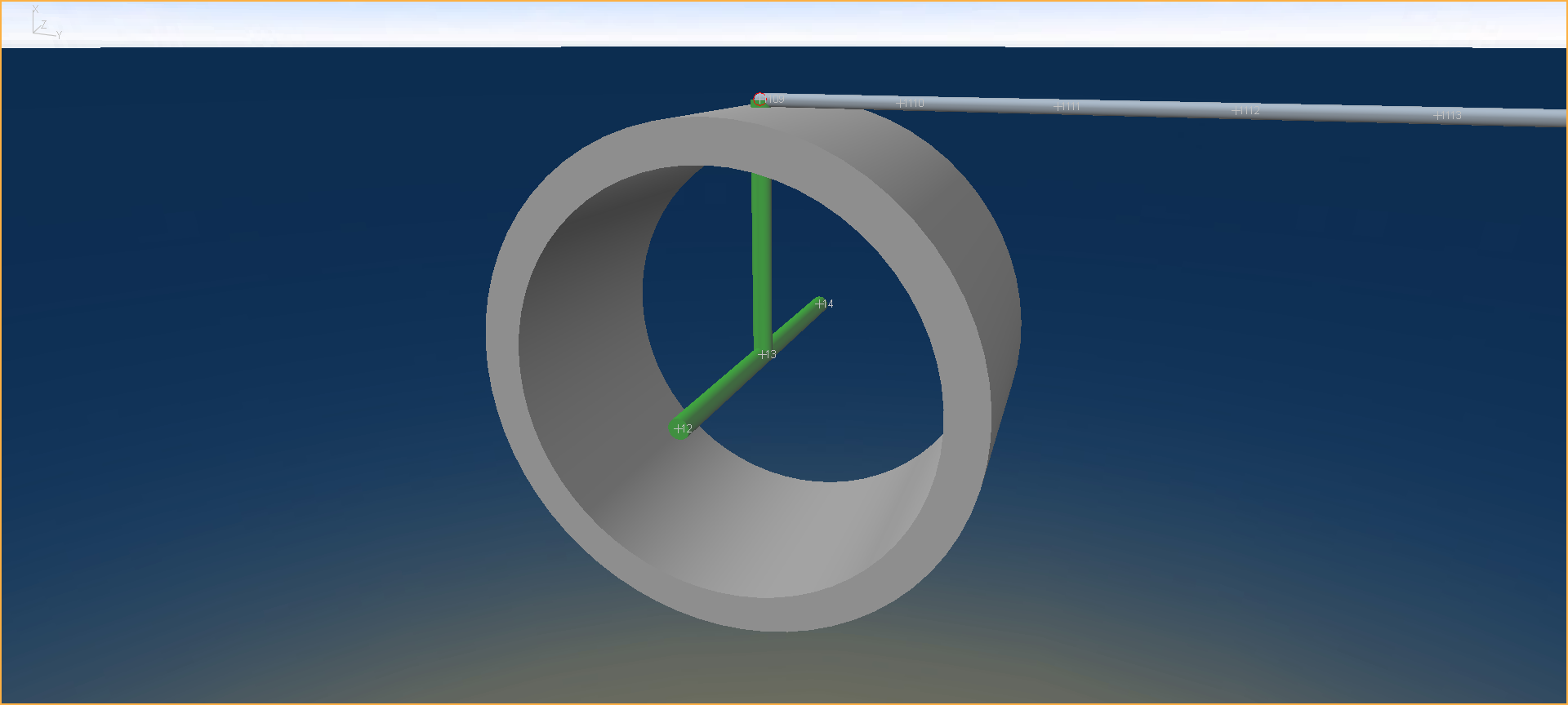
The upper end of the cable is attached to a rigid frame within the tower pulley. The frame and pulley are rotated at a constant speed using a vessel time history file, causing the cable to wrap itself around the contact surface.

Tower Pulley with Rotating Internal Frame
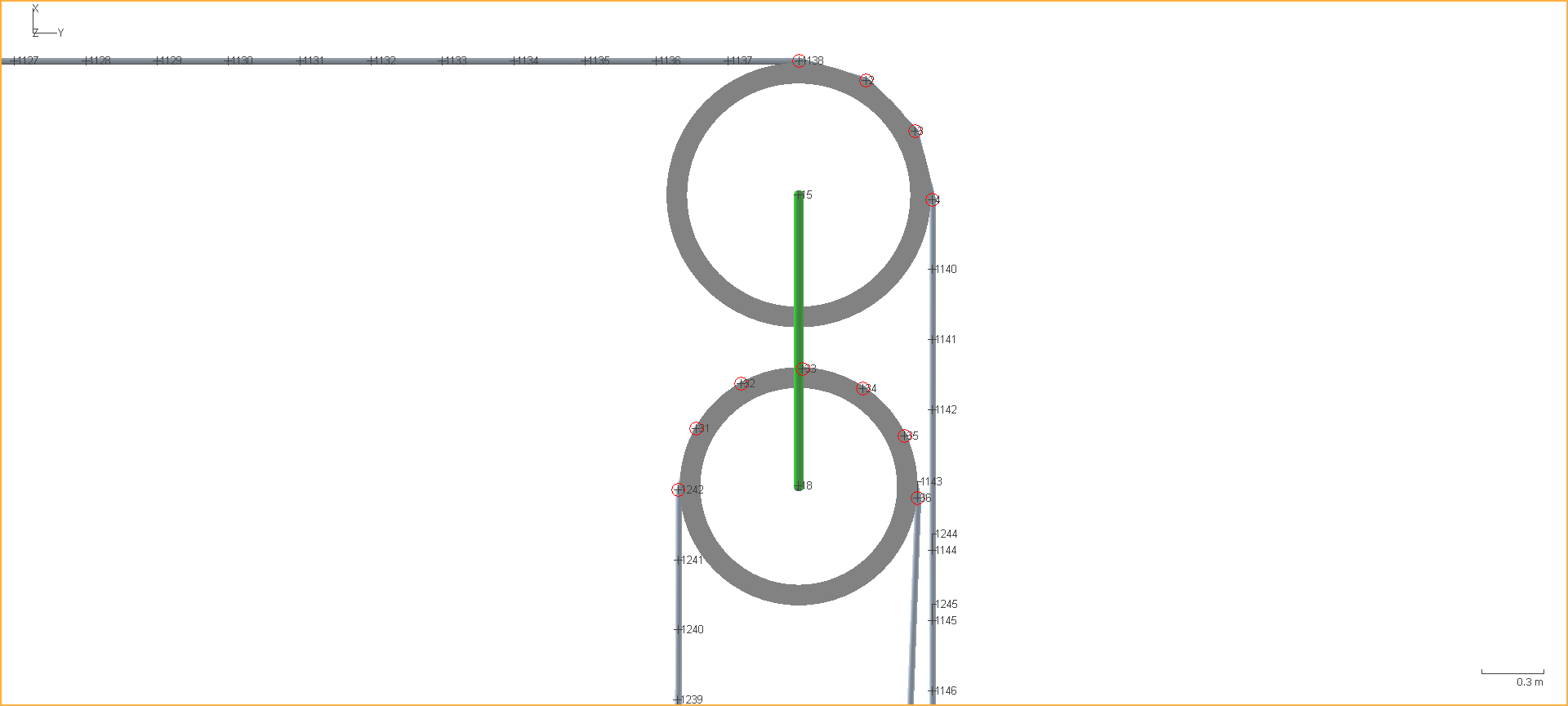
The cable profile is constructed using a series of straight lines between the pulleys which are meshed automatically, and several (partial) circular sections which position the cable around the pulleys and which are meshed manually using explicit nodes and elements. The straight and circular sections are connected together using the equivalent nodes feature.
The mesh density is relatively fine in order to model the cable-pulley interaction in sufficient detail. Element lengths of 0.34m are used throughout the model, equating to 12 nodes around a full pulley circumference, like points on a clock face.

Linear and Circular Meshes
The pulleys are attached to their respective supporting frames via the GUIDE keyword, and the pulley frames are fixed using the BOUNDARY keyword. Had the tower crane been modelled explicitly using beam elements, the pulley frames would simply form part of the tower structure, which would be constrained at its base.
The block is restrained initially using temporary boundary condition before being released in a quasi-static stage to allow the cable-pulley interactions to fully develop.