|
*Guide |
 
|
*Guide
|
*Guide |
|
To define guide (contact) surfaces.
Refer to Contact Surfaces for further information on this feature.
There are three possible types of guide surface: flat guides, cylindrical guides and zero-gap guides. The keyword formats are slightly different in each case, so each one is described separately.
A block of lines that defines a flat guide surface, repeated as often as necessary.
The first line defines the guide type:
TYPE=FLAT
It is possible to associate the guide surface with a vessel or a structural node, or for the guide to remain stationary. The format of the second line is…
NAME=Guide Name, VESSEL=Vessel Name, SET=Set Name
or...
NAME=Guide Name, NODE=Node (Number or Label), SET=Set Name
or...
NAME=Guide Name, SET=Set Name
The format of the remaining lines is as follows:
X0, Y0, Z0
X1, Y1, Z1, X2, Y2, Z2
h, w [, Characteristic Length] [, Thickness] [, Contact Zone Depth]
[μlong] [, μtran], k
Refer to the relevant table entries for a detailed discussion of each of these parameters. If you specify a node label rather than a number, it must be enclosed in {} brackets. X0, Y0 and Z0 are the global X, Y, & Z coordinates of the origin of the contact surface. X1, Y1 and Z1 are the global X, Y, & Z components of a vector that describes the local x-axis of the surface. X2, Y2 and Z2 are the global X, Y, & Z components of a vector that describes the local y-axis of the surface. h and w are the height and width of the surface, respectively. µlong and µtran are the longitudinal and transverse friction coefficients, respectively. k is the elastic contact stiffness of the surface.
A block of lines that defines a cylindrical guide surface, repeated as often as necessary.
The first line defines the guide type and surface contact type. By default, contact is with the external cylindrical surface:
TYPE=CYLINDRICAL [, SURFACE=EXTERNAL]
For contact with the internal cylindrical curved surface the format is:
TYPE=CYLINDRICAL [, SURFACE=INTERNAL]
It is possible to associate the guide surface with a vessel or a structural node, or for the guide to remain stationary. The format of the second line is…
NAME=Guide Name, VESSEL=Vessel Name, SET=Set Name
or...
NAME=Guide Name, NODE=Node (Number or Label), SET=Set Name
or...
NAME=Guide Name, SET=Set Name
The format of the remaining lines is as follows:
[AXIS=Axis System]
Xo, Yo, Zo
Xa, Ya, Za
Xr, Yr, Zr
L, R, [Θ], ϕ [, Thickness]
K
[μaxial] [, μcirc] [, Characteristic Length]
Refer to the relevant table entries for a detailed discussion of each of these parameters. If you specify a node label rather than a number, it must be enclosed in {} brackets. You must use the *LOCAL AXIS SYSTEM keyword to define any local axis system you reference here. Xo, Yo and Zo are the X, Y, & Z coordinates of the origin of the contact surface. Xa, Ya and Za are the X, Y, & Z components of a vector that describes the local (longitudinal) axis of the cylinder. Xr, Yr and Zr are the X, Y, & Z components of a vector that describes the local radius of the cylinder. L and R are the length and radius of the cylinder, respectively. θ and ϕ are the starting angle and subtended angle of the cylindrical surface, respectively – these entries allow partial cylinders to be modelled. K is the elastic contact stiffness of the surface. µaxial and µcirc are the friction coefficients in the axial and circumferential directions, respectively.
A block of lines that defines a zero-gap guide surface, repeated as often as necessary.
The first line defines the guide type:
TYPE=ZEROGAP
For zero-gap guides, it is possible to associate the guide surface with a vessel or for the guide to remain stationary. The format of the second line is…
VESSEL=Vessel Name, SET=Set Name
or...
SET=Set Name
The format of the remaining lines is as follows:
X0, Y0, Z0
X1, Y1, Z1
Height [, Contact Zone Diameter] [, Display Diameter] [, Characteristic Length]
[μlong] [, Preload] [, Contact Stiffness]
[NODE POSITION LOCK=Switch] [NODE ROTATION LOCK=Switch]
Refer to the relevant table entries for a detailed discussion of each of these parameters. X0, Y0 and Z0 are the global X, Y, & Z coordinates of the origin of the zero-gap guide. X1, Y1 and Z1 are the global X, Y, & Z components of a vector that describes the orientation of the zero-gap guide. µlong is the longitudinal friction coefficient. Switch can be YES or NO.
Input: |
Description |
Guide Name: |
The name of the flat guide that will be referenced throughout the analysis. |
Set Name: |
The name of an element set that will be monitored during the analysis for contact with this guide surface. |
Vessel Name: |
The name of the vessel whose motions govern the movement of the guide. |
X0, Y0, Z0: |
Global X, Y, & Z coordinates of the origin of the contact surface at solution initiation. See Note (a). |
X1, Y1, Z1: |
The global X, Y, & Z components of a vector that describes the local x-axis of the surface at solution initiation. See Note (a). |
X2, Y2, Z2: |
The global X, Y, & Z components of a vector that describes the local y-axis of the surface at solution initiation. See Note (a). |
Height: |
The height (measured along the local x-axis) of the contact surface. |
Width: |
The width (measured along the local y-axis) of the contact surface. |
Thickness: |
The thickness (measured along the local z-axis) of the contact surface. This entry is used for display purposes only and does not affect the overall operation of the contact modelling algorithm. It is an optional entry and defaults to 0.1m or 0.328ft. |
Contact Zone Depth: |
The depth (measured along the local z-axis) of the contact zone. This entry defines a rectangular cuboid underneath the guide within which nodes are monitored for contact. This defaults to infinity, meaning that any node located within the guide height and width is deemed to be in contact, regardless of the vertical (local-z) separation between node and guide. |
muLong: |
The longitudinal friction coefficient associated with this guide surface. |
muTran: |
The transverse friction coefficient associated with this guide surface. |
Characteristic Length: |
The length to be used in determining the non-linear stiffness used to simulate frictional restraint. This entry is optional and defaults to 10% of the guide surface Height if omitted. |
Stiffness: |
The elastic contact stiffness of the surface. See Note (e). |
Input: |
Description |
Guide Name: |
The name of the flat guide that will be referenced throughout the analysis. |
Set Name: |
The name of an element set that will be monitored during the analysis for contact with this guide surface. |
Node: |
The node (number or label) whose motions govern the movement of the guide. If you specify a node label rather than a node number, it must be enclosed in {} brackets. |
X0, Y0, Z0: |
Global X, Y, & Z coordinates of the origin of the contact surface at solution initiation. See Note (a). |
X1, Y1, Z1: |
The global X, Y, & Z components of a vector that describes the local x-axis of the surface at solution initiation. See Note (a). |
X2, Y2, Z2: |
The global X, Y, & Z components of a vector that describes the local y-axis of the surface at solution initiation. See Note (a). |
Height: |
The height (measured along the local x-axis) of the contact surface. |
Width: |
The width (measured along the local y-axis) of the contact surface. |
Thickness: |
The thickness (measured along the local z-axis) of the contact surface. This entry is used for display purposes only and does not affect the overall operation of the contact modelling algorithm. It is an optional entry and defaults to 0.1m or 0.328ft. |
Contact Zone Depth: |
The depth (measured along the local z-axis) of the contact zone. This entry defines a rectangular cuboid underneath the guide within which nodes are monitored for contact. This defaults to infinity, meaning that any node located within the guide height and width is deemed to be in contact, regardless of the vertical (local-z) separation between node and guide. |
muLong: |
The longitudinal friction coefficient associated with this guide surface. |
muTran: |
The transverse friction coefficient associated with this guide surface. |
Characteristic Length: |
The length to be used in determining the non-linear stiffness used to simulate frictional restraint. This entry is optional and defaults to 10% of the guide surface Height if omitted. |
Stiffness: |
The elastic contact stiffness of the surface. See Note (e). |
Input: |
Description |
Guide Name: |
The name of the flat guide that will be referenced throughout the analysis. |
Set Name: |
The name of an element set that will be monitored during the analysis for contact with this guide surface. |
X0, Y0, Z0: |
Global X, Y, & Z coordinates of the origin of the contact surface at solution initiation. See Note (a). |
X1, Y1, Z1: |
The global X, Y, & Z components of a vector that describes the local x-axis of the surface at solution initiation. See Note (a). |
X2, Y2, Z2: |
The global X, Y, & Z components of a vector that describes the local y-axis of the surface at solution initiation. See Note (a). |
Height: |
The height (measured along the local x-axis) of the contact surface. |
Width: |
The width (measured along the local y-axis) of the contact surface. |
Thickness: |
The thickness (measured along the local z-axis) of the contact surface. This entry is used for display purposes only and does not affect the overall operation of the contact modelling algorithm. It is an optional entry and defaults to 0.1m or 0.328ft. |
Contact Zone Depth: |
The depth (measured along the local z-axis) of the contact zone. This entry defines a rectangular cuboid underneath the guide within which nodes are monitored for contact. This defaults to infinity, meaning that any node located within the guide height and width is deemed to be in contact, regardless of the vertical (local-z) separation between node and guide. |
muLong: |
The longitudinal friction coefficient associated with this guide surface. |
muTran: |
The transverse friction coefficient associated with this guide surface. |
Characteristic Length: |
The length to be used in determining the non-linear stiffness used to simulate frictional restraint. This entry is optional and defaults to 10% of the guide surface Height if omitted. |
Stiffness: |
The elastic contact stiffness of the surface. See Note (e). |
(a)Refer to Flat Guide Surfaces for a detailed discussion of contact modelling with flat guide surfaces.
(b)These tables are used to define the initial location and orientation of rectangular contact surfaces. Each contact surface has a local axis system associated with it, as shown below. The initial location and orientation of the contact surface is defined by specifying the initial coordinates of the origin of this axis system along with the local x- and y-axes.
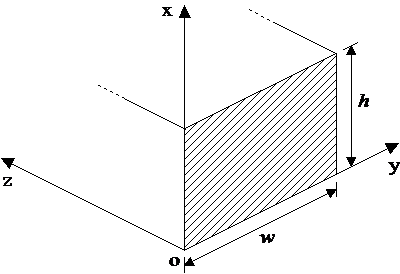
The origin of the contact surface is defined as the lower left-hand corner of the surface when the surface is viewed from the side that can come into contact with the structure. To define the local x- and y-axes, you must specify the global X, Y & Z components of two vectors, the first of which is aligned with the local x-axis and the second of which is aligned with the local y-axis. The length of these vectors is not significant – it is their orientation that is important. Naturally, there must be a 90° angle between the local x- and y-axes or the program will generate an error. Once the local x- and y-axes are specified, the program automatically finds the local-z axis using the right-hand rule. Note that the orientation of the local-z axis is significant – it must point away from the side of the surface that can come into contact with the structure
(c)If the contact surface has been associated with a vessel or node, then the initial location and orientation of the contact surface correspond to the initial position of that vessel or node. Any subsequent motions from the initial position will cause a corresponding movement of the contact surface.
(d)The longitudinal and transverse friction coefficients for the surface apply to contact with all elements in the contact element set associated with the surface. The Characteristic Length input relates to the operation of the guide surface friction model, and allows user control over the characteristics of non-linear springs used to model frictional restraint. For more information, refer to Guide Surface Friction Modelling.
(e)The flat guide is assumed to be a linear elastic surface. The contact stiffness should be specified in units of [Force] / [Distance] (for example N/m in metric or lb/ft in Imperial).
Input: |
Description |
Surface Contact: |
The cylindrical surface with which contact is to be made. This is either external (the default) or internal. |
Guide Name: |
The name of the cylindrical guide that will be referenced throughout the analysis. |
Set Name: |
The name of an element set that will be monitored during the analysis for contact with this guide surface. |
Vessel Name: |
The name of the vessel whose motions govern the movement of the guide surface. |
Axis: |
The name of a local axis system in which the contact surface geometry is defined. This entry is optional and the global axis system is used by default. See Note (b). |
Xo, Yo, Zo: |
The X, Y, & Z coordinates of the origin of the contact surface at solution initiation. The origin is located at the centre of curvature, at the first end of the cylinder. See Note (c). |
Xa, Ya, Za: |
The X, Y, & Z components of a vector that describes the local (longitudinal) axis of the cylinder at solution initiation. See Note (c). |
Xr, Yr, Zr: |
The X, Y, & Z components of a vector that describes the local radius of the cylinder at solution initiation. This vector must be orthogonal to the axial vector. See Note (c). |
Length: |
The length of the cylinder, measured along the axial vector. See Note (c). |
Radius: |
The radius of the cylinder, measured along the radial vector. See Note (c). |
Start Angle: |
The starting angle of the cylindrical surface, measured in a clockwise direction with respect to the radius vector, in a plane which is perpendicular to the axial vector. The Start Angle and Subtended Angle entries allow partial cylinders to be modelled. Start Angle is an optional entry, and defaults to half the Subtended Angle times minus one. See Notes (c) and (d). |
Subtended Angle: |
The subtended angle of the cylindrical surface, measured in a clockwise direction from the Start Angle, in a plane which is perpendicular to the axial vector. See Notes (c) and (d). |
Thickness: |
The thickness of the contact surface. This entry is used for display purposes only and does not affect the overall operation of the contact modelling algorithm. It is an optional entry and defaults to 0.1m or 0.328ft. For external contact it is measured from the external surface in. For internal contact it is measured from the internal surface out. |
Stiffness: |
The elastic contact stiffness of the surface. See Note (f). |
muAxial: |
The friction coefficient in the axial direction (i.e. parallel to the axial vector). |
muCirc: |
The friction coefficient in the circumferential direction (i.e. parallel to the surface tangent vector). |
Characteristic Length: |
The length to be used in determining the non-linear stiffness used to simulate frictional restraint. This entry is optional and defaults to 10% of the cylinder Length if omitted. See Note (g). |
Input: |
Description |
Surface Contact: |
The cylindrical surface with which contact is to be made. This is either external (the default) or internal. |
Guide Name: |
The name of the cylindrical guide that will be referenced throughout the analysis. |
Set Name: |
The name of an element set that will be monitored during the analysis for contact with this guide surface. |
Node: |
The node (number or label) whose motions govern the movement of the guide. If you specify a node label rather than a node number, it must be enclosed in {} brackets. |
Axis: |
The name of a local axis system in which the contact surface geometry is defined. This entry is optional and the global axis system is used by default. See Note (b). |
Xo, Yo, Zo: |
The X, Y, & Z coordinates of the origin of the contact surface at solution initiation. The origin is located at the centre of curvature, at the first end of the cylinder. See Note (c). |
Xa, Ya, Za: |
The X, Y, & Z components of a vector that describes the local (longitudinal) axis of the cylinder at solution initiation. See Note (c). |
Xr, Yr, Zr: |
The X, Y, & Z components of a vector that describes the local radius of the cylinder at solution initiation. This vector must be orthogonal to the axial vector. See Note (c). |
Length: |
The length of the cylinder, measured along the axial vector. See Note (c). |
Radius: |
The radius of the cylinder, measured along the radial vector. See Note (c). |
Start Angle: |
The starting angle of the cylindrical surface, measured in a clockwise direction with respect to the radius vector, in a plane which is perpendicular to the axial vector. The Start Angle and Subtended Angle entries allow partial cylinders to be modelled. Start Angle is an optional entry, and defaults to half the Subtended Angle times minus one. See Notes (c) and (d). |
Subtended Angle: |
The subtended angle of the cylindrical surface, measured in a clockwise direction from the Start Angle, in a plane which is perpendicular to the axial vector. See Notes (c) and (d). |
Thickness: |
The thickness of the contact surface. This entry is used for display purposes only and does not affect the overall operation of the contact modelling algorithm. It is an optional entry and defaults to 0.1m or 0.328ft. For external contact it is measured from the external surface in. For internal contact it is measured from the internal surface out. |
Stiffness: |
The elastic contact stiffness of the surface. See Note (f). |
muAxial: |
The friction coefficient in the axial direction (i.e. parallel to the axial vector). |
muCirc: |
The friction coefficient in the circumferential direction (i.e. parallel to the surface tangent vector). |
Characteristic Length: |
The length to be used in determining the non-linear stiffness used to simulate frictional restraint. This entry is optional and defaults to 10% of the cylinder Length if omitted. See Note (g). |
Input: |
Description |
Surface Contact: |
The cylindrical surface with which contact is to be made. This is either external (the default) or internal. |
Guide Name: |
The name of the cylindrical guide that will be referenced throughout the analysis. |
Set Name: |
The name of an element set that will be monitored during the analysis for contact with this guide surface. |
Axis: |
The name of a local axis system in which the contact surface geometry is defined. This entry is optional and the global axis system is used by default. See Note (b). |
Xo, Yo, Zo: |
The X, Y, & Z coordinates of the origin of the contact surface at solution initiation. The origin is located at the centre of curvature, at the first end of the cylinder. See Note (c). |
Xa, Ya, Za: |
The X, Y, & Z components of a vector that describes the local (longitudinal) axis of the cylinder at solution initiation. See Note (c). |
Xr, Yr, Zr: |
The X, Y, & Z components of a vector that describes the local radius of the cylinder at solution initiation. This vector must be orthogonal to the axial vector. See Note (c). |
Length: |
The length of the cylinder, measured along the axial vector. See Note (c). |
Radius: |
The radius of the cylinder, measured along the radial vector. See Note (c). |
Start Angle: |
The starting angle of the cylindrical surface, measured in a clockwise direction with respect to the radius vector, in a plane which is perpendicular to the axial vector. The Start Angle and Subtended Angle entries allow partial cylinders to be modelled. Start Angle is an optional entry, and defaults to half the Subtended Angle times minus one. See Notes (c) and (d). |
Subtended Angle: |
The subtended angle of the cylindrical surface, measured in a clockwise direction from the Start Angle, in a plane which is perpendicular to the axial vector. See Notes (c) and (d). |
Thickness: |
The thickness of the contact surface. This entry is used for display purposes only and does not affect the overall operation of the contact modelling algorithm. It is an optional entry and defaults to 0.1m or 0.328ft. For external contact it is measured from the external surface in. For internal contact it is measured from the internal surface out. |
Stiffness: |
The elastic contact stiffness of the surface. See Note (f). |
muAxial: |
The friction coefficient in the axial direction (i.e. parallel to the axial vector). |
muCirc: |
The friction coefficient in the circumferential direction (i.e. parallel to the surface tangent vector). |
Characteristic Length: |
The length to be used in determining the non-linear stiffness used to simulate frictional restraint. This entry is optional and defaults to 10% of the cylinder Length if omitted. See Note (g). |
(a)Refer to Cylindrical Guide Surfaces for a detailed discussion of contact modelling with cylindrical guide surfaces.
(b)If a local axis system referenced, it must be defined using the *LOCAL AXIS SYSTEM keyword.
(c)The overall layout of the cylindrical guide surface is illustrated by the following schematic.
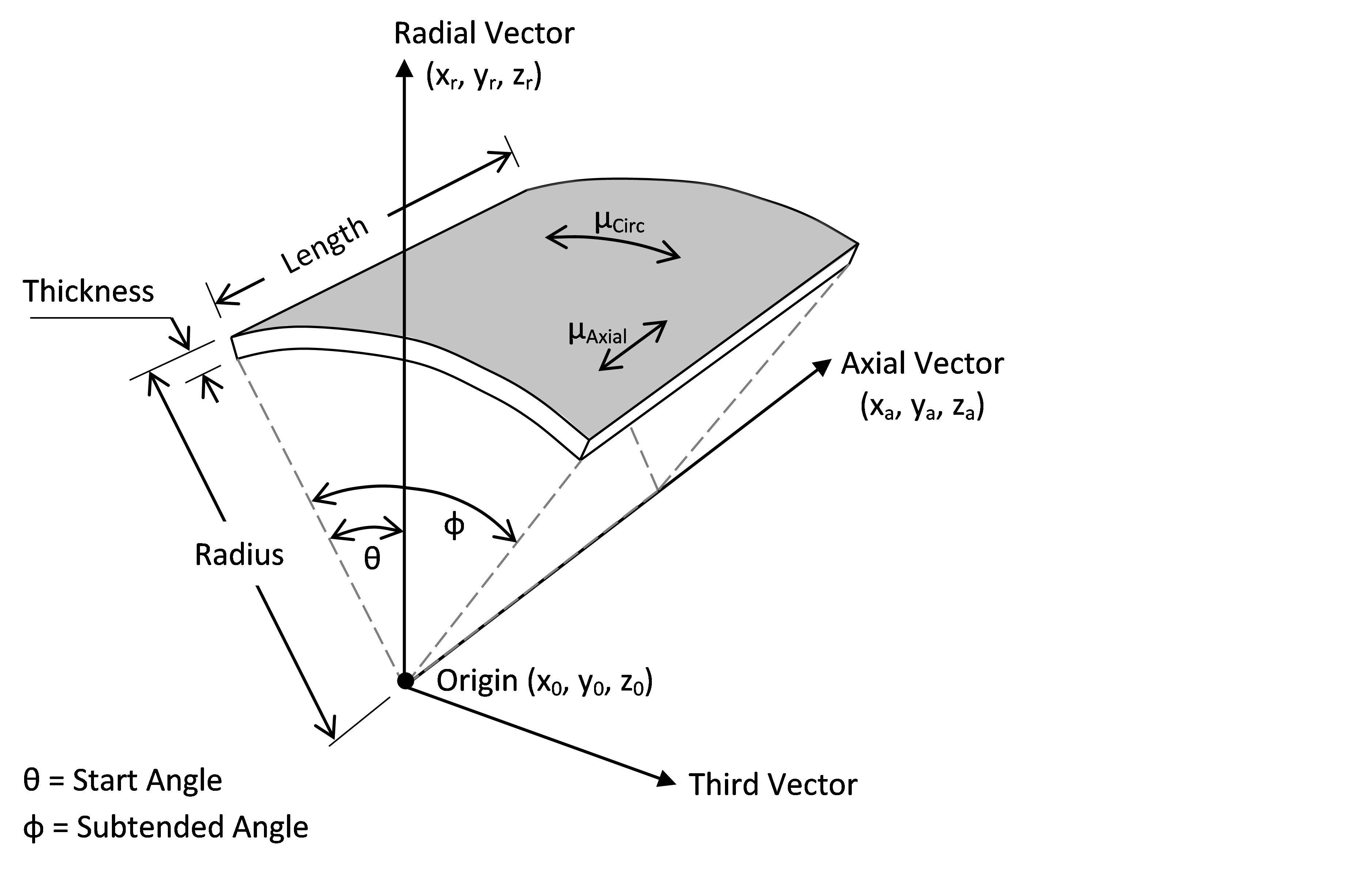
Each cylindrical surface has a local axis system associated with it, as shown above. The axial and radial vectors form two components of a right handed system. The length of these vectors is not significant – it is their orientation that is important. Naturally these two vectors should be orthogonal. A third vector is assembled internally using the right-hand rule.
(d)The sign convention for both the Start Angle and the Subtended Angle is consistent with the right handed system. Specifically, positive angles represent rotations of the radial vector toward the third vector. If a Start Angle is not specified, its magnitude is half that of the Subtended Angle, and it differs in sign. In this case, the radial vector bisects the Subtended Angle, and represents an axis of symmetry for the cylindrical surface.
(e)If the contact surface has been associated with a vessel or node, then the initial location and orientation of the contact surface correspond to the initial position of that vessel or node. Any subsequent motions from the initial position will cause a corresponding movement of the contact surface.
(f)The cylindrical guide is assumed to be a linear elastic surface. The contact stiffness should be specified in units of [Force] / [Distance] (for example N/m in metric or lb/ft in Imperial).
(g)The axial and circumferential friction coefficients for the surface apply to contact with all elements in the contact element set associated with the surface. The Characteristic Length input relates to the operation of the guide surface friction model, and allows user control over the characteristics of non-linear springs used to model frictional restraint. For more information, refer to Guide Surface Friction Modelling.
Input: |
Description |
Set Name: |
The name of an element set that will be monitored during the analysis for contact with this zero-gap guide. |
Vessel Name: |
The name of the vessel with which the zero-gap guide is associated. The guide translates and rotates with the vessel during the analysis. |
X0, Y0, Z0: |
Global X, Y, & Z coordinates of the origin of the zero gap guide at solution initiation. See Note (b). |
X1, Y1, Z1: |
The global X, Y, & Z components of a vector that defines the orientation of the zero-gap guide at solution initiation. See Note (b). |
Height: |
The height of the zero-gap guide. |
Contact Zone Diameter: |
A cylindrical region enclosing the guide within which nodes are monitored for contact. This defaults to infinity, meaning that any node located within the guide length is deemed to be in contact, regardless of the lateral separation between node and guide. See the cylindrical boundary shown in Note (b). |
Display Diameter: |
Zero-gap guides are displayed using auxiliary elements, sized using the display diameter specified here. If none is specified, the display size defaults to 0.1m or 0.1ft, depending on the unit system. |
Characteristic Length: |
The length to be used in determining the non-linear stiffness used to simulate frictional restraint. This entry is optional and defaults to 10% of the guide Height if omitted. |
muLong: |
The longitudinal friction coefficient associated with this guide surface. |
Preload: |
The static preload to be applied to the zero-gap guide. See Note (e). |
Stiffness: |
The elastic contact stiffness of the guide. |
Node Position Lock: |
This entry enables or disables the contact stiffness terms, including frictional restraint. |
Node Rotation Lock: |
This entry enables or disables rotational restraints on any node in contact with the guide. If switched on, any nodal rotations present when the node enters the guide are maintained (using boundary conditions) until the node leaves the guide. |
Input: |
Description |
Set Name: |
The name of an element set that will be monitored during the analysis for contact with this zero-gap guide. |
X0, Y0, Z0: |
Global X, Y, & Z coordinates of the origin of the zero gap guide at solution initiation. See Note (b). |
X1, Y1, Z1: |
The global X, Y, & Z components of a vector that defines the orientation of the zero-gap guide at solution initiation. See Note (b). |
Height: |
The height of the zero-gap guide. |
Contact Zone Diameter: |
A cylindrical region enclosing the guide within which nodes are monitored for contact. This defaults to infinity, meaning that any node located within the guide length is deemed to be in contact, regardless of the lateral separation between node and guide. See the cylindrical boundary shown in Note (b). |
Display Diameter: |
Zero-gap guides are displayed using auxiliary elements, sized using the display diameter specified here. If none is specified, the display size defaults to 0.1m or 0.1ft, depending on the unit system. |
Characteristic Length: |
The length to be used in determining the non-linear stiffness used to simulate frictional restraint. This entry is optional and defaults to 10% of the guide Height if omitted. |
muLong: |
The longitudinal friction coefficient associated with this guide surface. |
Preload: |
The static preload to be applied to the zero-gap guide. See Note (e). |
Stiffness: |
The elastic contact stiffness of the guide. |
Node Position Lock: |
This entry enables or disables the contact stiffness terms, including frictional restraint. |
Node Rotation Lock: |
This entry enables or disables rotational restraints on any node in contact with the guide. If switched on, any nodal rotations present when the node enters the guide are maintained (using boundary conditions) until the node leaves the guide. |
(a)Refer to Zero-Gap Guide Surfaces for a detailed discussion of contact modelling with zero-gap guide surfaces.
(b)The initial location and orientation of the guide is defined by specifying the initial coordinates of the origin of the guide along with an orientation vector, as shown below.
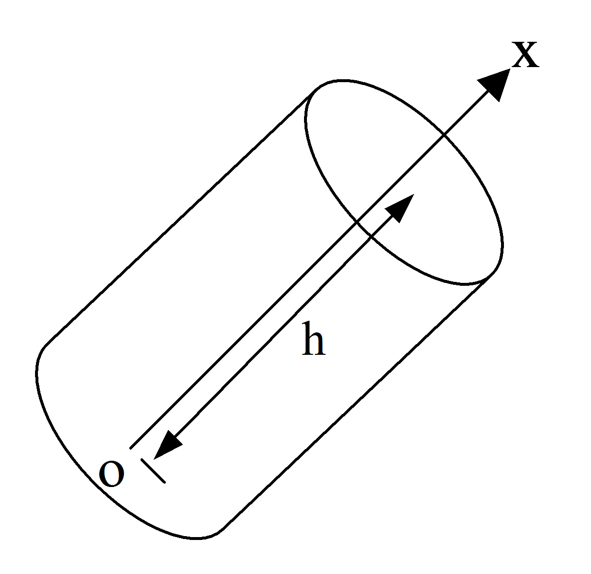
The origin of the zero-gap guide is defined as the centre point of one end (usually bottom) of the guide. To define the orientation vector, you must specify its global (X, Y & Z) components. The length of this vector is not significant – it's the orientation which is important
(c)If the zero-gap guide has been associated with a vessel, then the initial location and orientation of the zero-gap guide correspond to the initial position of that vessel. Any movement of the vessel from its initial position (including movement due to offset, drift, or vessel RAOs) will cause a corresponding movement of the zero-gap guide.
(d)The longitudinal friction coefficient for the zero-gap guide apply to contact with all elements in the contact element set associated with the zero-gap guide.
(e)A static preload may be optionally applied to a zero-gap guide. If a preload is specified, the limiting frictional force, Flim, in the longitudinal direction at a given node in contact with the zero-gap guide is defined as:
![]()
where μ is the longitudinal friction coefficient, Rn is the magnitude of the reaction force at the constrained node, and Pn is the preload associated with the contact node. The user specified preload, P, for the guide is distributed evenly between all nodes which are in contact with the guide at any given time, such that:
![]()
where N is the number of nodes in contact with the guide. If no static preload is specified, the limiting frictional force is computed in the usual way as:
![]()
(f)Restraint provided by the guide is modelled using elastic stiffness terms. The contact stiffness is specified in units of [Force] / [Distance] (e.g. N/m or lb/ft).
(g)The Characteristic Length input relates to the operation of the guide friction model, and allows user control over the characteristics of non-linear springs used to model frictional restraint. For more information, refer to Guide Surface Friction Modelling.