Flat Guide Surfaces |
 
|
Flat Guide Surfaces |
|
Each flat guide is a rectangular surface. To define a flat guide surface, it is necessary to specify the following pieces of information:
(i)Whether the guide surface is to be associated with a vessel or a structural node, or if it is to remain stationary throughout the analysis.
(ii)The name of a set of elements that are to be monitored for contact with the guide surface. In most analyses, only a small section of the model is ever likely to come into contact with a particular guide surface, and for this reason it is, in general, unnecessary to check every node in the model for contact with a guide surface at every timestep. By associating a set of elements with each guide surface, the number of nodes that must be checked at each solution time is significantly reduced. This leads to faster analyses.
(iii)The location of the flat guide surface at the start of the analysis. This is specified by inputting the global coordinates of a particular point on the flat guide surface at the start of the initial analysis.
(iv)The orientation of the flat guide surface at the start of the analysis. This is defined by specifying the global components of two vectors that lie in the plane of the surface.
(v)The dimensions (height & width) of the flat guide surface.
(vi)The longitudinal and transverse friction coefficients associated with the contact surface.
(vii)The elastic contact stiffness of the guide surface.
Each contact surface has a local axis system associated with it, as shown in the figure below. The initial location and orientation of the contact surface is defined by specifying the initial coordinates of the origin of this axis system along with the local x- and y-axes.
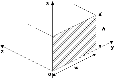
Flat Guide Surface
The origin of the contact surface is defined as the lower left-hand corner of the surface when the surface is viewed from the side that can come into contact with the structure. To define the local x- and y-axes, you must specify the global X, Y & Z components of two vectors, the first of which is aligned with the local x-axis and the second of which is aligned with the local y-axis. The length of these vectors is not significant – it is their orientation that is important. Naturally, there must be a 90° angle between the local x- and y-axes or the program will generate an error. Once the local x- and y-axes are specified, the program automatically finds the local-z axis using the right-hand rule. Note that the orientation of the local-z axis is significant – it must point away from the side of the surface that can come into contact with the structure.
•*GUIDE is used to define guide (contact) surfaces. Specifically, the TYPE=FLAT inputs are used to define flat guide surfaces.