The University of Maine (UMaine) VolturnUS-S reference semi-submersible (Allen et al., 2020) is a generic steel version of the UMaine patented concrete floating foundation technology developed in collaboration with the U.S. Department of Energy (Viselli et al., 2016). According to UMaine, “the reference design aims to serve the wind industry by providing a publicly available design benchmark to explore new technologies and design methodologies while facilitating collaboration between industry and researchers”.
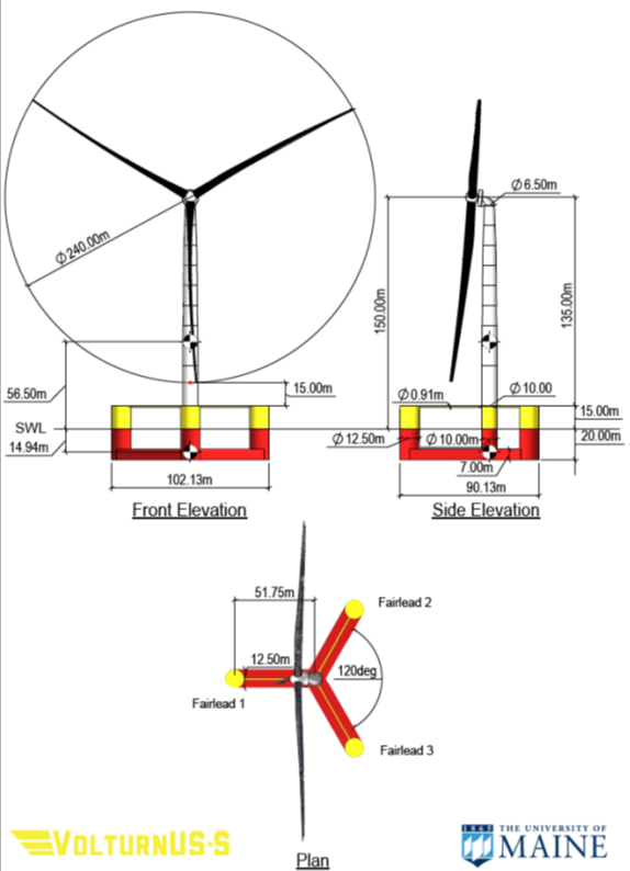
The hull comprises three 12.5m-diameter buoyant columns radially spaced with centres that are 51.75m from the tower’s vertical axis. The platform-tower interface is atop a fourth buoyant column located at the centre of the platform in the surge-sway plane. This central column is connected to the outer columns via three 12.5m-wide-by-7.0m-high rectangular bottom pontoons and three 0.9m-diameter radial struts attached to the bottom and top of the buoyant columns, respectively. When on station, the total mass of the platform is 17,854t, of which 3,914t is structural steel, 2,540t is fixed iron-ore-concrete ballast, divided equally and placed at the base of the three radial columns, 11,300t is seawater ballast that floods the majority of the three submerged pontoons, and a 100t tower interface connection
The mooring system consists of three 850m-long chain catenary lines. Each line is connected at the fairlead to one of the platform’s three outer columns at a depth of 14m below the SWL. The lines span radially to anchors spaced equally at 120 degrees in the surge-sway plane, which are located at a depth of 200m and spaced radially 837.6m from the tower’s centreline. All lines use a studless R3 chain with a nominal (bar) diameter of 185mm.

Schematic of UMaine semisub (Allen et al., 2020)
A summary of the semi-sub’s main characteristics is presented here, and further details are available in Allen et al., 2020.
Parameter |
Value |
Parameter |
Value |
|---|---|---|---|
Column length |
35m |
Platform mass |
17,854 t |
Central column diameter |
10m |
Hull steel mass |
3,914 t |
Offset column diameter |
12.5m |
Ballast mass (Fixed, Fluid) |
2,540t, 11,300t |
Radial spacing to offset columns |
51.75m |
Tower interface mass |
100t |
Pontoon width |
12.5m |
Roll inertia |
1.251E+10 kg.m2 |
Pontoon height |
7.0m |
Pitch inertia |
1.251E+10 kg.m2 |
Freeboard |
15m |
Yaw inertia |
2.367E+10 kg.m2 |
Draft |
20m |
||
Overall size (length, width, height) |
88.0m, 103.0m, 35.0m |
||
Strut diameter |
0.9m |
||
CoG (from SWL) |
-14.94m |
||
CoB (from SWL) |
-13.63m |
The IEA Wind 15 MW wind turbine was jointly developed by the National Renewable Energy Laboratory (NREL) and the Technical University of Denmark (DTU). This reference wind turbine is a Class IB direct-drive machine, with a rotor diameter of 240m and a hub height of 150m. Full details of the turbine, supported by a fixed-bottom monopile, are presented by Gaertner et al. 2020, and a summary of key parameters are presented here. The wind turbine uses a direct-drive layout with a permanent-magnet, synchronous, radial flux outer-rotor generator in a simple and compact nacelle layout.
Parameter |
Value |
Parameter |
Value |
|---|---|---|---|
Power rating |
15 MW |
Maximum tip speed |
95 m/s |
Turbine class |
IEC Class 1B |
Rotor diameter |
240 m |
Specific rating |
332 W/m2 |
Airfoil series |
FFA-W3 |
Rotor orientation |
Upwind |
Hub height |
150 m |
Number of blades |
3 |
Hub diameter |
7.94 m |
Control |
Variable speed Collective pitch |
Hub overhang |
11.35 m |
Cut-in wind speed |
3 m/s |
Rotor precone angle |
-4.0 deg |
Rated wind speed |
10.59 m/s |
Blade prebend |
4 deg |
Cut-out wind speed |
25 m/s |
Blade mass |
65 t |
Design tip-speed ratio (TSR) |
9.0 |
Drivetrain |
Direct drive |
Minimum rotor speed |
5.0 rpm |
Shaft tilt angle |
6 deg |
Maximum rotor speed |
7.56 rpm |
Rotor nacelle assembly (RNA) mass |
1,017 t |
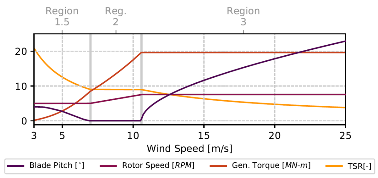
The NREL Reference OpenSource Controller (ROSCO) is used to control the turbine. Two active proportional integral (PI) controllers are implemented for the generator torque and blade pitch angles. The controller operation can be distinguished by three regions:
•3 m/s <= U <= 6.98 m/s; minimum rotor speed. A PI controller on the generator torque is used to regulate the turbine to the turbine’s minimum rotor speed, 5 rpm. The minimum blade pitch angle is defined based on a wind speed estimate, such that CP is maximized.
•6.98 m/s <= U <= 10.59 m/s; optimal TSR. In below-rated wind speeds, the rotor speed is regulated to operate at the turbine’s optimal TSR with a PI controller on the generator torque.
•10.59 m/s <= U <= 25 m/s; rated power. In above-rated wind speeds, the rotor speed is regulated to its rated value, 7.55 rpm, via a PI controller on the blade pitch angle.
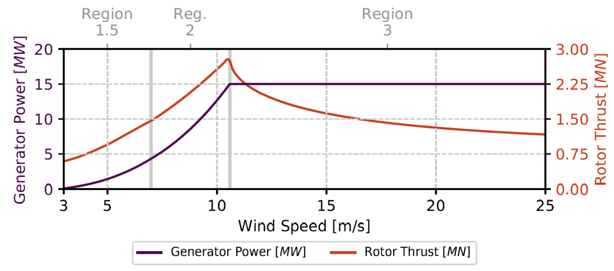
The steady-state performance of the rotor as a function of wind speed is shown below, along with the power and thrust curves for the turbine. In Region 1.5, minimum rotor speed constraints result in significantly higher, suboptimal tip-speed ratios. The blade pitch controller imposes a minimum pitch constraint based on the wind speed estimate, so that CP is maximized. This results in positive blade pitch angles of up to 4° at low wind speeds. Concurrently, the generator torque controller attempts to set the rotor to the minimum rotor speed. In Region 2, the torque controller tracks the set point tip-speed ratio, which is set near or at maximum CP. The design point for this blade is TSR = 9.0 and blade pitch = 0°. Finally, in Region 3, the torque controller is saturated at rated torque and the blade pitch PI controller pitches to feather to maintain rated rotor speed.

Controller Regulation (Gaertner et al. 2020)

Power & Thrust Curves (Gaertner et al. 2020)
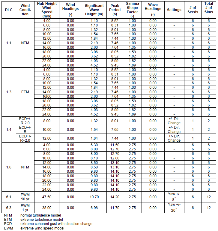
A subset of IEC design load case conditions was selected by UMaine to gauge the performance of the reference semisub in representative normal and extreme design conditions (based on industry standard IEC 61400-1, 2020). According to UMaine, the simulations were selected to represent governing conditions of various critical components of the floating offshore wind turbine based on design experience of similar systems. All conditions considered an aligned wind and wave heading of 0 degrees (head seas). The environmental conditions associated with the design cases are representative of the U.S. East Coast.
The design load cases considered may be summarised as follows:
DLC |
Turbine |
Wind |
Wave |
|---|---|---|---|
1.1 |
Power production |
Normal Turbulence Model (NTM) Vin < Vhub < Vout |
Normal Sea State Hs = E[Hs|Vhub] |
1.3 |
Power production |
Extreme Turbulence Model (ETM) Vin < Vhub < Vout |
Normal Sea State Hs = E[Hs|Vhub] |
1.4 |
Power production |
Extreme Coherent Gust with Direction Change (ECD) Vhub = Vr–2m/s, Vr, Vr+2m/s |
Normal Sea State Hs = E[Hs|Vhub] |
1.6 |
Power production |
Normal Turbulence Model (NTM) Vin < Vhub < Vout |
Severe Sea State Hs = Hs,SSS |
6.1 |
Parked |
Extreme Wind Model Vhub = V10min,50-yr |
Extreme Sea State Hs = Hs,50-yr |
6.3 |
Parked |
Extreme Wind Model Vhub = V10min,1-yr |
Extreme Sea State Hs = Hs,1-yr |
Design load cases 1.1, 1.3 & 1.6 are reproduced in Example L04, but you are free to simulate other cases in your own time. In order to achieve this, you should examine the load case spreadsheet (L4-DLCs.xlsx) and expand this appropriately. You can then modify the *EXCEL VARIATIONS keyword in the master template files (L4-DLCs.keyxm). This will allow you to produce all the required keyword files. Note also that for efficiency reasons, this example considers only one value of wind and wave seed while the UMaine simulations typically consider 6 seeds, so again you will need to expand the spreadsheet if you wish to overcome this limitation.
Further details regarding the construction of the design load cases are provided by Allen et al., 2020 and reproduced here.

IEC Design Load Case Matrix (Allen et al., 2020)
The required wind data files for Example L04 are not shipped with Flexcom. The binary files tend to be very large, so it is not practical to include these in the installation package. Instead, you can readily generate the files yourself with the Wind Field Generator app. You will find a sample project file for the app in the Data->Wind subfolder of the project, it is called L4-DLCs-Wind.wfproj. It is already pre-populated with the relevant wind speeds and turbulence models etc., so all you need to do is select the File->Generate Input Files and Run TurbSim command.