Introduction |
 
|
Introduction |
|
This example considers the analysis of an oil offloading facility which includes a steel offloading line and a CALM buoy. Complex systems such as these which are characterised by hydrodynamic and mechanical coupling between components have traditionally been designed by analysing the individual components in isolation. The displacements of the individual floating components, most notably the CALM buoy, would have been calculated from RAOs derived for model tests and/or radiation/diffraction analyses. However, such an approach has the potential to be highly conservative. Typically for example the inertia of the offloading line or lines is of a similar order of magnitude to the CALM buoy, so the presence of these lines affects the buoy response in a way that would not be captured in the derivation of RAOs.
A better solution is to use a coupled analysis approach, and this is facilitated by the Flexcom CALM buoy facility and illustrated in this example. ‘Coupled’ in this context means that the CALM buoy is explicitly included in the model, and its motions are calculated from forces and reactions on the buoy, including those from the buoy mooring lines and the offloading lines, rather than from RAOs. Further details on the actual model used and the analyses performed are provided in the next sections. The figure below shows the system under consideration. The material in the example is based on a publication by Connaire et al., (2003).
This example illustrates a number of important modelling features in Flexcom, specifically:
•The CALM Buoy facility, which calculates the high frequency response of a floating buoy subject to first order wave forces.
•The Truss Element, which is ideally suited to modelling mooring chains and wires.
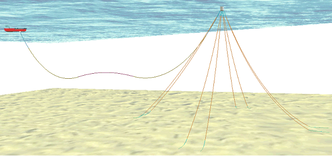
CALM Buoy Offloading System