Linear Motion Power Take-Off |
 
|
Linear Motion Power Take-Off |
|
Input: |
Description |
Initial Length: |
The overall length of the power-take off device in its initial configuration. In other words, its maximum length is equal to the sum of the initial length plus the upper end stop distance |
Upper End Stop Distance: |
The maximum extension of the power-take off device before it reaches its end stop, relative to its initial position. This entry is optional and if omitted, no upper end stop is modelled. |
Lower End Stop Distance: |
The maximum contraction of the power-take off device before it reaches its end stop, relative to its initial position. This entry is optional and if omitted, no lower end stop is modelled. |
Diameter: |
The physical diameter of the power-take off device, assuming a cylindrical shape. This entry is optional, and is used for visualisation purposes only. |
(a)The power-take off mechanism is represented as a cylindrical piston-and-sleeve type device in Flexcom. In terms of a physical device, this modelling approach is suitable for hydraulic or pneumatic pistons, or linear electric generators.
(b)The end stops govern the range of free movement of the mechanism, as discussed further in Stiffness.
(c)The Diameter input relates to the size of the outer sleeve. While it has no structural function, it provides a useful visualisation of the power-take off mechanism in operation. The diameter of the piston is assumed to be equal to half that of the sleeve.
Input: |
Description |
Constant Damping Force: |
The constant damping force applied by the power-take off. This entry is optional and if omitted, no constant damping force is modelled. |
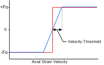
Velocity Threshold: |
A velocity threshold below which the constant damping term is linearly ramped. This entry is optional and if omitted, the constant damping force is applied at all times. See Note (b). |
Linear Damping Coefficient: |
The linear damping coefficient for the power-take off. This entry is optional and if omitted, no linear damping term is modelled. |
Quadratic Damping Coefficient: |
The quadratic damping coefficient for the power-take off. This entry is optional and if omitted, no quadratic damping term is modelled. |
(a)Flexcom models the damping aspects of the power take-off using a non-linear damper element. The axial force exerted by the damper element, F, is defined as follows:
![]()
where ![]() is the relative velocity between the element end nodes in the axial direction of the element, F0 is the constant damping force, and C1 & C2 are the linear and quadratic damping coefficients respectively.
is the relative velocity between the element end nodes in the axial direction of the element, F0 is the constant damping force, and C1 & C2 are the linear and quadratic damping coefficients respectively.
(b)It is possible to control the application of the constant damping force (F0 term) by specifying a velocity threshold. By default no ramping is applied, so the damping force is applied in full at all times. The significance of the velocity threshold is illustrated in the figure below. Rather than switching instantaneously between positive and negative force values, the constant force term is gradually ramped up over a finite range of relative velocity. This tends to smooth out the applied damping forces and eliminates the possibility of a dramatic alternation between positive and negative force terms for small extensions and contractions of the damper element.
Velocity Threshold
Input: |
Description |
Constant Force: |
The constant spring force applied by the power-take off. This entry is optional and if omitted, no constant force is modelled. |
Extension Stiffness: |
The standard resistive stiffness of the power-take off in regions of free movement. This entry is optional and if omitted, the extension stiffness term is assumed to be zero. |
Upper End Stop Stiffness: |
The high resistive stiffness of the power-take off device as the device reaches its upper end stop. This entry is optional and if omitted, no upper end stop is modelled. |
Lower End Stop Stiffness: |
The high resistive stiffness of the power-take off device as the device reaches its lower end stop. This entry is optional and if omitted, no lower end stop is modelled. |
Upper End Stop Ramp Length: |
The length of a transition region between the extension stiffness and the upper end stop stiffness. This entry is optional and if omitted, there is an instantaneous change in slope of the stiffness curve at the transition point. |
Lower End Stop Ramp Length: |
The length of a transition region between the extension stiffness and the lower end stop stiffness. This entry is optional and if omitted, there is an instantaneous change in slope of the stiffness curve at the transition point. |
(a)Flexcom models the stiffness aspects of the power take-off using a non-linear spring element. In regions of free movement, the restoring force provided by the spring element, F, is defined as follows:
![]()
where F0 is the constant spring force, KFM is the extension stiffness, and x is the extension in the spring element.
(b)As the spring extends or contracts towards its end stop limits, the spring stiffness is increased to the end stop stiffness over the end stop ramp length to provide a high level of resistance to any further motion. For example, at the end of the upper end stop transition region, the restoring force, F, provided by the spring element is defined as follows:
![]()
where KES is the upper end stop stiffness, and xES is the upper end stop distance.
Input: |
Description |
Conversion Efficiency Factor: |
A power conversion efficiency factor which accounts for the losses between the generated mechanical power and the electrical power output. |