3D Seabed Profile |
 
|
3D Seabed Profile |
|
In the context of Flexcom seabed contact, a 3D seabed profile is defined by a set of 3D scattered data points which lie on the seabed surface. The global XYZ coordinates of the points on the seabed surface must be specified by the user through the Seabed Utility application which then precompiles the data and generates a binary file (with a file extension of .FCSBD) that can be referenced in a Flexcom analysis.
The 3D seabed file that is generated by the seabed utility is used for:
•Rendering the seabed in the Model View.
•Modeling contact with the seabed during analyses.
See the Seabed Utility section for further details on how to pre-compile a compatible 3D seabed file.
At a high level, the compilation process involves a number of steps described as follows:
(i) The seabed data points are read from an input text file.
(ii) A Delaunay triangulation on the Flexcom global YZ coordinates of the data points is performed. The resulting triangulation ensures that no data point is inside the circumcircle of any triangle. For example, on the left hand side of the figure below is given the global YZ locations of a set of input data points. There are two possible triangulations of this data as shown in the center and on the right. The Delaunay triangulation of the four points must be the one shown on the right because no data point lies within the circumcircles of the triangles.
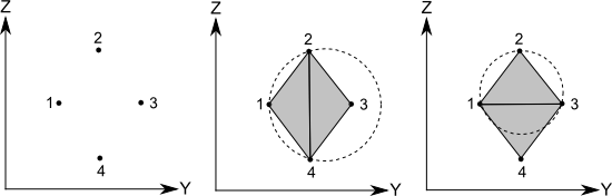
Delaunay Triangulation.
(iii) Surface gradients are then determined at each data point for cubic interpolation.
(iv) To render a nonlinear 3D seabed surface in the Model View, the data is further subdivided into regularly spaced points. A Delaunay triangulation is again performed over this new set of gridded points as shown in the figure below and elevations are calculated using the nonlinear interpolation. The grid interval length is chosen based on the user’s maximum triangle side requirement.
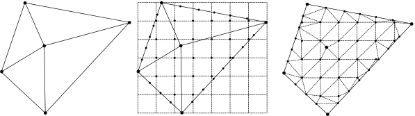
Mesh Subdivision for Rendering of Nonlinear 3D Seabed
(v) Finally, gradient and triangulation data both for analysis and rendering purposes is written to the seabed file.
Once the seabed file has been generated it may be referenced in a keyword file under the *SEABED PROFILE keyword. The type of interpolation to be used is specified here also and can be linear or cubic.
If linear interpolation is selected then the triangles formed during the Delaunay triangulation of the input data form the surface of the seabed. The elevation of each triangle vertex is that specified by the user input data global X coordinate. The elevation of interpolation points whose YZ coordinate lies within a particular triangle is interpolated linearly on the plane of that triangle as shown on the left of the figure below.
If cubic interpolation is selected then the triangles formed during the Delaunay triangulation of the input data are used to determine the surface of the seabed. The elevation of each triangle vertex is that specified by the user input data global X coordinate. The elevation of interpolation points whose YZ coordinate lies within a particular triangle is interpolated on a cubic surface over that triangle using the data point surface gradients determined during the seabed file creation process. The cubic surface is defined so that neighbouring triangle edges and gradients are continuous as shown on the right of the below figure.

Linear and Cubic 3D Seabed Interpolation.
Finally, the 3D seabed is assumed to be infinitely deep outside the bounds of the triangulation.
•*SEABED PROFILE is used to specify the seabed profile/bathymetry.
•*SEABED PROPERTIES is used to specify properties such as seabed type (i.e. rigid or elastic) and friction parameters.
If you would like to see an example of a 3D seabed profile, refer to H04 - Pipe Laying.