Subsea Buoys |
 
|
Subsea Buoys |
|
Many offshore structures have subsea buoyancy structures incorporated into their design. How these structures are modelled can have a significant effect on the outcome of analyses. This relates in particular to the hydrodynamic properties of the buoy, since modelling the correct buoyancy force is relatively straightforward.
To facilitate the accurate modelling of subsea buoyancy structures, such as a subsea buoy/arch arrangement in a flexible riser lazy-S configuration, Flexcom incorporates a Buoy Structure facility. You use this facility to assign the properties that define the hydrodynamic response of the buoy to a set of elements that collectively represent the buoy.
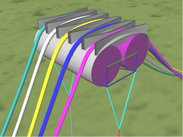
Typical Subsea Buoy
A typical subsea buoy is shown in the figure above. Obviously the hydrodynamic properties vary depending on direction. For this reason the buoy hydrodynamic coefficients are normally specified separately for each of three directions (one vertical, two horizontal). Furthermore, for each direction the data is often specified as three products, namely i) CdAd (drag coefficient by frontal area), for the hydrodynamic loading due to relative fluid/buoy velocity; ii) CmVin (inertia coefficient by reference volume), for the hydrodynamic loading due to water particle acceleration; and iii) CaVin (added mass coefficient by reference volume), for the hydrodynamic loading due to buoy acceleration. This means a subsea buoy may be characterised by nine hydrodynamic coefficients or products.
The basic modelling procedure in Flexcom is that a subsea buoy is modelled using an assemblage of beam elements. All of these elements are then combined into one or more element sets in the usual way. Finally, the buoy hydrodynamic properties are specified for each buoy structure element set. The figure below shows a sample assemblage of beam elements.
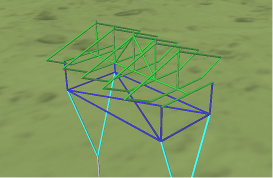
Assemblage of Beam Elements
What happens in the actual Flexcom analysis is that the program computes the overall loading on the buoy, and then distributes the forces to the constituent elements. In this way phase differences between wave forces on different parts of the buoy, and also the changes in the buoy hydrodynamic properties as the buoy displaces and rotates, are accurately modelled.
It should be noted that each element of the buoy structure is a normal beam element in its own right, and must have structural (geometric) properties assigned to it in the usual way. Typically the beam elements are rigid, and broadly speaking, approximate the mass distribution around the structure.
If the primary axes of the buoy structure happen to be aligned with the global XYZ axes of the software model, then the Global axis system option should be used. However, in many cases it will be necessary to define a Local axis system, which describes how the buoy structure is initially aligned with respect to the global XYZ coordinate system. Typically the local X axis will coincide with the global X axis, as the buoy will be horizontal initially, and local Y and Z axes will reflect the orientation of the buoy.
With regard to the treatment of axis system, improvements to the software, first introduced in Flexcom 8.3.5, are noteworthy. In earlier versions, the user did not explicitly define the local axis system. Rather the program assumed it to be coincident with the local axis system of the buoy structure elements. Given that several elements are typically contained within the buoy structure element set, the potential for conflicting definitions was ever present. So the hydrodynamic force terms could only be modelled correctly if (i) a single element was used to model the buoy structure, or (ii) several elements aligned in a uniform direction were used. Potential discrepancies have since been eliminated via the explicit specification of the local axis system.
Hydrodynamic forces on the buoy structure are computed via Morison’s Equation. Three separate force terms (i.e. drag, added mass and added inertia) are computed in three separate directions, based on the user-specified hydrodynamic coefficients, and the instantaneous structural and fluid motions. These forces are computed with respect to the local buoy structure axis system, and then rotated into the global axis system. Even if the buoy is initially aligned with the global axis system (i.e. the Global specification option is used), some rotation is usually necessary as the buoy structure will displace and rotate over time subject to the hydrodynamic excitation induced by environmental loading.
The total forces are distributed evenly amongst the constituent elements, based on their projected lengths onto the local XY, YZ & XZ planes of the buoy structure. Consider drag loading in the local X direction as an example. Each element will be projected onto the local YZ plane, where it will be assigned a certain projected length. This length, expressed as a percentage of the total sum of all the projected lengths, governs the fraction of the total force which is applied to any given element. For the simple case of a cuboid shown in the below figure, the total force in the vertical (X) direction is distributed amongst the horizontal elements which border the upper and lower faces of the cuboid. The vertical elements which border the side faces receive no loading in this direction.
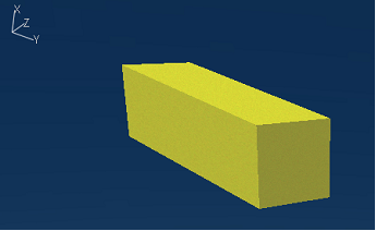
Drag Loading on Cuboid Shape
•*HYDRODYNAMIC SETS is used to assign hydrodynamic coefficients to element sets. Specifically, the TYPE=BUOY input is used to assign hydrodynamic properties to a set of elements that collectively model a subsea buoy.
If you would like to see an example of how this keyword is used in practice, refer to C02 - Multi-Line Flexible System.