Cable Pre-Static Step |
 
|
Cable Pre-Static Step |
|
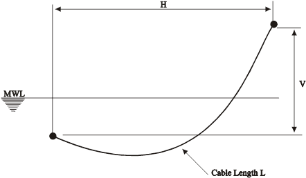
The use of the cable pre-static step is best illustrated by means of an example. Suppose that you want to perform an analysis of a simple free hanging catenary system such as that shown in the Example Catenary Configuration below. For simplicity, assume that you require the static configuration due to gravity and buoyancy only. What you would know in advance of setting up this analysis would be the length of the cable, the various cable properties (mass and stiffness, assumed uniform for simplicity), and the horizontal and vertical distances between the catenary end points (denoted H and V on the Example Catenary Configuration). How would you then go about performing this analysis?

Example Catenary Configuration
Obviously the cable profile is part of the solution sought, so defining the finite element nodal coordinates using only the standard features described earlier (define directly and generate on a straight line) presents difficulties. Using this method the best option would be to locate one end of the cable at some arbitrary position in which the cable is stretched out in a straight line, such as that shown in the Initial Static Analysis below This position is easy to calculate, and specification of the nodal coordinates is then straightforward. However, an initial analysis must now be performed to move this end into its required starting position. Although this procedure is perfectly valid in Flexcom, it does add an additional step simply to arrive at the required starting position. For complicated and/or sensitive systems, performing this initial static solution can sometimes prove difficult.
Initial Static Analysis
The Flexcom pre-static step is designed to eliminate this unwanted analysis stage. The procedure in the example above would be as follows. Firstly, you would define the coordinates of the start and end nodes in the actual initial static configuration shown in the above Example Catenary Configuration. You would then specify that the structure forms a cable of specified length between these points. You would next use the options for Defining Nodes In Terms Of Cables to distribute nodes along the cable, although its profile is not yet known. Following specification of the connectivity, properties and remaining data, you would run Flexcom. The program pre-static step would run automatically, and calculate an initial estimate of the locations of the catenary intermediate nodes using the cable catenary equations, neglecting bending and torsion. These estimates would then be passed to the main analysis module, which would solve the full finite element equations with bending and torsion included, for the actual static configuration. Convergence would typically be achieved in a small number of iterations.