Sample Application: Pipeline Model |
 
|
Sample Application: Pipeline Model |
|
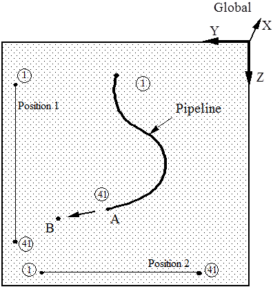
Consider the situation below, which shows a plan view of a pipeline lying on the seabed (which for convenience is assumed here to be smooth). Suppose the initial position shown by the heavy line can be defined in terms of the nodal coordinates of, say, Nodes 1 to 41, but that it is now required to examine the effect on the pipeline of pulling Node 41 from Point A to Point B. How might this analysis be performed in Flexcom?
When Initial is Not Undeformed
Specification of the nodal coordinates (presumed known) and finite element connectivity is straightforward. Obviously though the initial position defined by these coordinates cannot represent a stress free configuration. The pipeline is stress free when it is stretched out in a straight line to its full length, and this is what Flexcom needs to be told. Where the pipe actually is in space when stretched out is of no consequence. For example, either of the positions identified as Position 1 or Position 2 above could be considered the stress free position of the pipeline. Motion of the pipeline from either to the initial position of the analysis induces the same stresses. Conversely, motion from Position 1 to Position 2 or vice versa induces no stresses in the pipe, since so-called ‘rigid body motions’ do not result in stresses. What Positions 1 and 2 have in common is that in both the elements all have the same relative orientation, and this is what is important. This is the reason why Flexcom requires you to specify vectors defining the stress free element orientation, rather than coordinates defining stress free position.