Undeformed Orientation Specification |
 
|
Undeformed Orientation Specification |
|
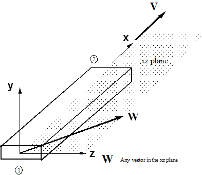
Obviously three vectors make up the local undeformed axes, but knowledge of two of them is sufficient because the three are orthogonal. This is why Flexcom requires only the specification of the components of two vectors, V and W. The V vector defines the x axis, that is, it is directed from the first node of the element to the second node, in the undeformed position. W is then any vector in the xz plane (other than V obviously). This definition of V and W is illustrated below. Note that neither V nor W is required to be a unit vector, nor are they required to be orthogonal (though they frequently are). While W can be any vector is the xz plane, a vector directed along the z axis is often a natural choice.
Consider again the sample pipeline model. For Position 1, V could be defined as (0, 0, 1) (directed along global Z) and for Position 2 as (0, -1, 0) (directed along negative global Y). For W, suitable choices for Position 1 could be (-1, 0, 0) and for Position 2 (0, 0, 1). In actual fact, in light of the above, the actual choices for V and W are nearly immaterial. The important thing is that all elements have the same undeformed orientation.