Vessel Heading |
 
|
Vessel Heading |
|
Current coefficient, wind coefficient, and QTF data, is specified as a function of the relative “heading” between the vessel and, respectively, current, wind and waves (QTFs are of course also defined as a function of wave frequency). It is important to be clear on the definition of “heading” for these inputs which is slightly different from the definition of “vessel heading” which applies to the input of first order vessel motion RAOs.
Dealing first with current, the coefficients are described as being defined as a function of Relative vessel/current heading, or of the angle of incidence of the current relative to the vessel axes. This “heading” is in fact the equivalent current incidence ![]() defined previously in Current Loads, earlier in this note. For the case of a Static Mooring analysis, the vessel CoG velocity components
defined previously in Current Loads, earlier in this note. For the case of a Static Mooring analysis, the vessel CoG velocity components ![]() and
and ![]() are both 0, so
are both 0, so ![]() is simply (
is simply (![]() - θ) that is, the global current direction minus the instantaneous vessel orientation. This is simply the current direction relative to the vessel surge axis, measured positive anti-clockwise from the positive axis direction. The figure below illustrates this definition schematically. Note that in strict mathematical terms the Relative vessel/current heading is the angle, positive anti-clockwise, from the positive direction of the local surge axis to the current direction drawn at the CoG.
- θ) that is, the global current direction minus the instantaneous vessel orientation. This is simply the current direction relative to the vessel surge axis, measured positive anti-clockwise from the positive axis direction. The figure below illustrates this definition schematically. Note that in strict mathematical terms the Relative vessel/current heading is the angle, positive anti-clockwise, from the positive direction of the local surge axis to the current direction drawn at the CoG.
The current coefficient sign at a particular heading should naturally reflect the direction of the current force for that heading. For example, a current with a heading of 180° would be expected to apply a force to the vessel along the negative direction of the local surge axis. So the current coefficient in surge for this heading would typically be negative.
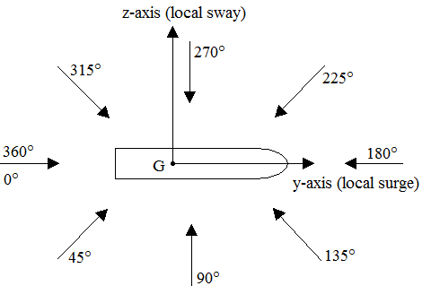
Definition of Relative Vessel/Current Heading
Likewise wind coefficients are described as being a function of Relative vessel/wind heading, or of the angle of incidence of the wind relative to the vessel axes. This “heading” is likewise the equivalent wind incidence ![]() defined previously in Wind Loads. For the case of a Static Mooring analysis,
defined previously in Wind Loads. For the case of a Static Mooring analysis, ![]() is simply (
is simply (![]() -
- ![]() ), that is, the global wind direction minus the instantaneous vessel orientation, which is again simply the wind direction relative to the vessel surge axis, positive anti-clockwise from the positive direction of the axis.
), that is, the global wind direction minus the instantaneous vessel orientation, which is again simply the wind direction relative to the vessel surge axis, positive anti-clockwise from the positive direction of the axis.
Finally, QTFs are described as being defined as a function of Relative vessel/wave heading, or of the angle of incidence of the wave relative to the vessel axes. This is the quantity ![]() used in Wave Drift Loads. Again this is simply the wave harmonic direction relative to the vessel surge axis, measured positive anti-clockwise from the positive axis direction. In strict mathematical terms the Relative vessel/wave heading is the angle from the positive direction of the local surge axis to the wave harmonic direction drawn at the CoG. In this the definition is slightly different to that used in defining RAOs, which is detailed in Vessels and Vessel Motions. There the incident wave heading for the definition of RAOs is defined as the angle between the wave direction drawn at the vessel reference point and the negative direction of the local surge axis.
used in Wave Drift Loads. Again this is simply the wave harmonic direction relative to the vessel surge axis, measured positive anti-clockwise from the positive axis direction. In strict mathematical terms the Relative vessel/wave heading is the angle from the positive direction of the local surge axis to the wave harmonic direction drawn at the CoG. In this the definition is slightly different to that used in defining RAOs, which is detailed in Vessels and Vessel Motions. There the incident wave heading for the definition of RAOs is defined as the angle between the wave direction drawn at the vessel reference point and the negative direction of the local surge axis.
Finally, it is important to define current and wind coefficients and QTFs over the full range of headings likely to be experienced in an analysis, as a value of zero is assumed for each of these parameters outside of the range of headings you specify. Headings values should ideally cover the full range from 0o to 360o. Likewise QTFs should be defined over a comprehensive range of frequencies, as a value of 0 will again be assigned to a QTF at a wave frequency outside of the range of values used in the data definition.