Finite Element Mesh |
 
|
Finite Element Mesh |
|
A zero-gap guide may be thought of as a sheath positioned around a section of riser, with a contact clearance of zero between the guide and the riser. The zero-gap contact algorithm differs from the corresponding flat/cylindrical guide procedure. If a node comes into contact with a zero-gap guide, appropriate boundary conditions are applied at the node in local axes which are both perpendicular to the longitudinal direction. The node is free to move in the axial direction (subject to frictional restraints) through the zero-gap guide, and whenever the node leaves the guide, the boundary conditions are removed.
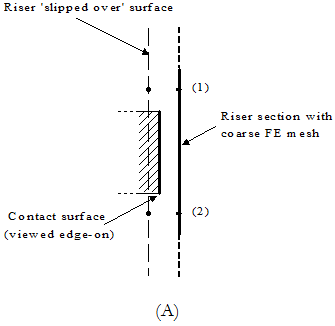
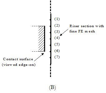
Because the contact algorithm is based on monitoring the position of nodes, it is important that the finite element mesh in sections of the riser that may come into contact with guide surfaces is sufficiently fine to properly model contact. For example, the figure below (A) shows a section of riser adjacent to a flat guide contact surface (which is being viewed edge-on and is represented by the heavy black line). Clearly, the finite element mesh in the riser is not sufficiently fine to model contact – with this model, the riser could ‘slip-over’ the guide surface as illustrated. The figure below (B) shows a more suitable mesh – it is obvious that, in this case, contact between the riser and the guide surface will be modelled correctly.
To properly model contact between a riser and a guide surface, it is desirable that the finite element mesh be such that at least two nodes of the riser are in contact with the guide surface when contact occurs. So the element length in the region of contact should be no more than half the appropriate dimension of the guide surface. This requirement for a fine finite element mesh in the region of contact must also be balanced against the requirement to keep the overall number of elements in the model to a practical level. For this reason, an element length in the range of one half to one third the appropriate dimension of the guide surface appears optimal.
Finite Element Meshes for Surface Contact
•*GUIDE is used to define guide (contact) surfaces.
•*LINES is used to define a line (and sections within that line), by specifying relevant set names, lengths, start and end locations, and mesh generation settings.