Model Building |
 
|
Model Building |
|
The lines functionality is a relatively recent addition to Flexcom, and essentially provides an automatic mesh creation facility whereby nodes, elements and cables can be generated quite easily. Using lines to build your model is a fundamentally different approach to working directly with nodes, elements and cables. While all the information is ultimately handled in the same fashion internally in the software, the use of lines expedites the model creation process considerably, as you need not concern yourself with individual node and element numbering. While the explicit numbering scheme (which was the only approach available in earlier versions of Flexcom) may appear obsolete by comparison, it is retained for complete generality, and also to maintain downward compatibility with previous versions. Refer to Lines for further information on this feature.
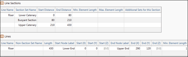
The Riser, including the Lower Catenary, Buoyant Section and Upper Catenary are modelled using a single line running all the way from the seabed to the base of the ship.
The line is called Riser, and is assigned a length of 430m. Its start and end locations are called Lower End {0m, 0m} and Upper End {210m, 430m}. Obviously the structural properties of the structure vary along its length due to the different components, so it is necessary to define a number of subsections in terms of distances along the line. The subsections are called Lower Catenary (from 0m to 80m), Buoyant Section (from 80m to 210m) and Upper Catenary (from 210m to 430m). The definition of the Riser line in both table and keyword editor is shown in below.
Input data is organised into two main categories, model data and load case data. This distinction is reflected in both the table and keyword editors. Model data consists of information which must be specified at the start of a series of consecutive analyses. This data is carried through to all subsequent restart analyses and may not be changed. This category naturally includes the finite element discretisation, structural and hydrodynamic properties, plus any other inputs which characterise the initial model configuration (e.g. initial vessel position, seabed properties, ocean depth etc.). Load case data may be entered in any analysis of a series of runs, and which may be subsequently altered in restart analyses. This category naturally includes environmental loading such as current and waves, boundary conditions, solution variables etc. There is a clear division between model and load case data in the keyword editor, via the $MODEL and $LOAD CASE sections in the keyword file. Similarly, in the table editor, the sections are split onto different tabs named MODEL and LOAD CASE. Before you enter the first keyword (i.e. *LINES, to define the central structure), you should include a $MODEL section entry. You can also add a MODEL section through the table editor by right-clicking on the table editor and selecting Add Section from the context menu.
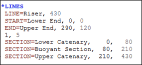
Central Structure Line
Refer to*LINES for further information on these data inputs.
The above construction method is fairly standard, where a smeared approach is adopted in terms of modelling riser buoyancy. In reality the central section of the riser is likely to be supported by a series of discrete buoyancy modules, rather than a continuous section of buoyancy foam. Modelling discrete buoyancy modules requires a little more effort, but assistance is provided by the *LINE SECTION GROUPS keyword which facilitates the creation of repeating sub-sections. A separate static input file is included in the example folder to illustrate this modelling approach. Although not used subsequently in terms of the dynamic simulation in this particular example, you may be interested to learn about this alternative modelling approach.
In this case, three separate lines are used to model the Lower Catenary, Middle Catenary and Upper Catenary. A line section group is assembled, comprising of a section of bare riser, a buoyancy module, and another bare riser section. The Middle Catenary line is then assembled using repeated occurrences of the line section group. Nodal equivalences are used to connect the lines together at the intersection points.
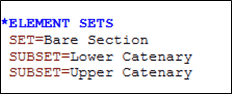
Flexcom uses the concept of element sets to define the physical properties of the finite element model. Groups of similar elements are logically combined into named element sets, properties are then assigned on an element set-by-set basis. When lines are utilised during model creation, relevant element sets are created automatically, based on the names of each line (and subsection of each line if appropriate) in the model.As the Lower Catenary and Upper Catenary have identical structural properties, a single element set called Bare Section is created to group both of these sections together.
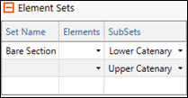
Element sets
Refer to *ELEMENT SETS for further information on these data inputs.
The Model View provides a “live” structure preview facility available during model building. It also allows you to view an animation of the structure response after an analysis has completed. The Model View allows you to rotate and pan the viewpoint, to zoom in and out, and has many other useful display features (feel free to experiment) such as node and element numbering, nodal coordinates, seabed topography, water surface profile etc. Once the geometric specification has been completed, the Model View provides a preview of the steep wave riser, as shown in the figure below. Refer to Model View for further information on this feature.
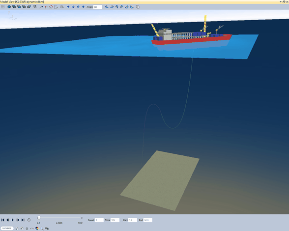
Model View