3D Seabed File |
 
|
3D Seabed File |
|
A new 3D seabed file can be created by selecting the appropriate option from the main menu or the program toolbar.
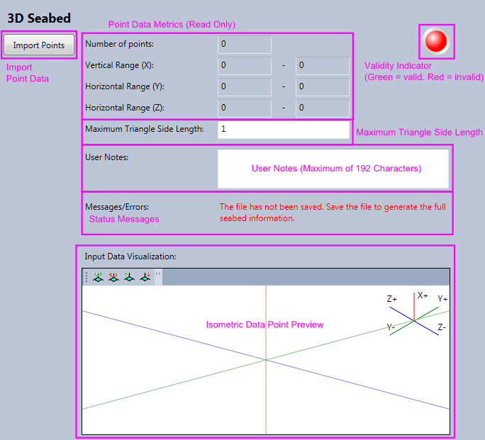
The screenshot below shows the seven areas on the 3D seabed screen:
1. A button to import data points.
2. Metrics on imported data points; count and ranges.
3. An entry for the maximum triangle side length to use when discretising the data for visualisation purposes.
4. An area to enter and edit user notes.
5. A validity indicator which shows if the seabed file is valid for using in a Flexcom analysis.
6. An area where status messages are displayed.
7. A 3D isometric preview of the imported data points.
Creating a 3D seabed requires the input of a series of (X, Y, Z) data points. Pressing the “Import Points” button allows you to select a text-based file and offers flexible import options, very much in the manner of Excel’s Text Import Wizard. The order of the data point components in the text file must conform to the Flexcom global coordinate system where the X axis represents elevation and the Y axis and Z axis represent orthogonal horizontal displacement.
For the rendering of a nonlinear 3D Seabed, you may wish to change the maximum triangle side length. This value is automatically set, based on the input data, to give a reasonably detailed nonlinear seabed rendering mesh while at same time ensuring that the seabed file size is not excessively large. This value should, ideally, be less than the horizontal distance between the closest pair of input data points to give a realistic 3D rendering of the nonlinear surface. If this value is too large then the rendered nonlinear seabed will appear unrealistic and contact nodes may appear to penetrate or lie above the seabed surface. If this value is too small, the compilation time may be excessively long and the compiled file size extremely large. It is important to note that this input value has an effect on the 3D model display only and has no bearing on the internal analysis seabed contact computations.
You can also enter User Comments. This block is limited to 192 characters and can be used to record any information you wish about the file.
On the upper-right of the display, the coloured indicator shows if the file is currently valid for use in a Flexcom analysis. For a new file, or a file just edited, this will appear red to indicate the file is not currently valid as it has not yet been compiled. Once the file is saved, provided there is no error in the compilation, the indicator should turn to green. If it is still red, an error message will appear under Messages/Errors. Alternatively, hovering over the indicator will show the current error as a tooltip. Review your input data first and if necessary contact software support for further assistance.
The isometric data point preview offers a simple isometric projection of the input data points to aid in checking the input data. Points are slightly depth faded to improve comprehensibility; points closer appear darker and those further away appear lighter. The vertical rotation of the isometric plot can be toggled between the four pre-set viewing angles using the first two toolbar buttons. The isometric tilt can also be varied using the second two toolbar buttons.