Global Degrees of Freedom |
 
|
Global Degrees of Freedom |
|
The independent components required to define the movement or displacement of a point on a structure are known as its degrees of freedom, or DOFs for short. A point requires 6 DOFs to define its movement – three translations (one vertical, two horizontal) and three rotations. In the Flexcom convention, a movement or displacement in the global X direction is denoted a DOF 1 translation, a displacement in global Y is a DOF 2 translation, while DOF 3 is used for a translation in the global Z direction.
The rotational displacements are denoted DOFs 4-6 in Flexcom. Explaining what these represent physically is a little more complicated than the translations case. Taken together, they represent the rotation in 3D space of a point from its initial orientation. You will no doubt be aware that finite (non-infinitesimal) 3D rotations cannot be represented as vectors, since the addition of such vectors is non-commutative, that is, the order in which the rotations are taken affects the result. In Flexcom this problem is handled by means of a consistent 3D kinematics formulation based on the correspondence between a specially defined rotation vector and a transformation matrix. Manipulation of the rotation is undertaken by means of operations on the transformation matrices. (You will note that as required matrix multiplication is non-commutative.)
The cornerstone of this formulation is the definition of the rotation vector referred to above. The full details are omitted here, but, in summary, a rotation is represented by a vector such that i) the magnitude of the vector represents the magnitude of the rotation, and ii) the direction of the vector represents the axis of rotation. DOFs 4-6 in Flexcom are the components of this rotation vector. This means that in general they do not represent individual rotations about the global X, Y and Z axes.
While this is true in general, in many cases the situation is somewhat simplified. Firstly, in an analysis where the structure and environment are in either the XY or XZ plane, then in this 2D case there is obviously only one rotation component active (for example, DOF 6 if structure and environment are in the vertical XY plane, as illustrated below).
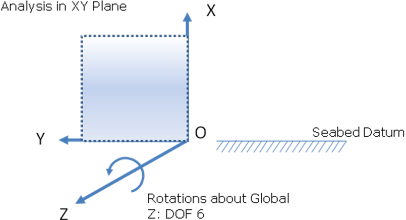
2D Analysis in XY Plane
Secondly, in a 3D analysis, the individual components will represent individual rotations about the global axes if the overall rotation is ‘small’, say less than 10°. See below, which shows incidentally the positive sense of these rotations.
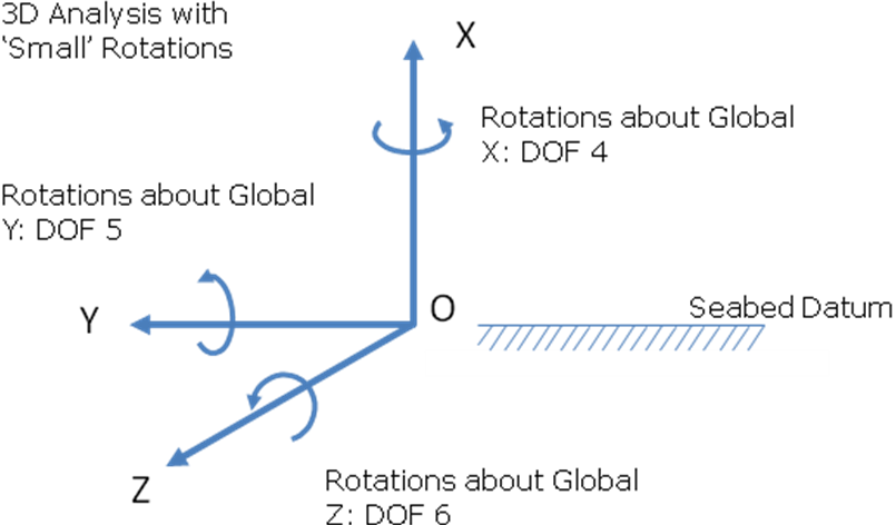
3D Analysis with Small Rotations
The only time the Flexcom user really needs to be aware of these rotation definitions and conventions is if you are applying non-zero rotational restraints or boundary conditions. It is important if specifying displacements in DOFs 4-6 to understand the significance of these degrees of freedom, as described above, and to be clear that they do not in the most general case represent individual rotations about the global axes. In particular, this means you should be wary of specifying only 1 or 2 rotation components (that is, 1 or 2 only of DOFs 4-6) where large rotations are involved, and you should only do so if you understand exactly the effect of what you are doing. Of course, if you are not specifying non-zero rotational boundary conditions, then this is not an issue.